
Building Construction: 1D elements are used in structural engineering for analyzing and designing buildings. They help determine the behavior of beams, columns, and frames under different loading conditions, ensuring structural integrity and safety. Bridge Design: 1D elements are employed in the analysis and design of bridges, allowing engineers to assess the structural performance and behavior of bridge components, such as beams and trusses, under different loads and environmental conditions. Heat Exchangers: 1D elements are utilized in the design and analysis of heat exchangers, which are devices used for transferring heat between fluids. They help determine the temperature distribution and heat transfer rates within the exchanger, ensuring efficient heat exchange. Electrical Circuits: 1D elements, such as resistors, inductors, and capacitors, are crucial components in electrical circuit analysis. They enable engineers to understand the behavior and performance of circuits, such as power distribution systems, electronic devices, and communication networks. Environmental Studies: 1D elements are employed in environmental modeling to study the transport of pollutants, contaminants, or heat in different media, such as soil, water, or air. They assist in analyzing the dispersion and movement of substances, aiding environmental impact assessments and remediation strategies. These are just a few examples of the widespread applications of 1D finite elements in various engineering and scientific disciplines. The behavior of many systems can be effectively simplified as one-dimensional, allowing for efficient and accurate analysis using 1D finite elements. At Artem Academy, we offer comprehensive courses that cover not only 1D finite elements but also 2D and 3D models. In our blogs, we dive into the fascinating world of 2D and 3D finite element analysis, unveiling their applications in simulating and understanding complex systems. Whether you are dealing with structural mechanics, fluid dynamics, heat transfer, or electromagnetics, our blogs provide valuable insights into how to leverage 2D and 3D finite elements for accurate predictions and optimization. To develop your understanding and enhance your skills, we invite you to join our courses at Artem Academy. Our expert instructors will guide you through the theoretical foundations and practical aspects of finite element analysis, equipping you with the tools to tackle real-world engineering challenges confidently. From mastering meshing techniques to interpreting simulation results, our courses empower you to become a proficient analyst in 1D, 2D, and 3D simulations. Stay connected with our blogs, explore the diverse applications of finite element analysis, and embark on a transformative learning journey with Artem Academy.
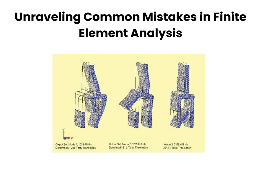
Finite Element Analysis (FEA) is one of the most powerful tools for analyzing and simulating simple to complex engineering problems in any industrial field. But cause of some common mistakes in Finite Element Analysis (FEA) can lead to inaccurate results and misleading interpretations. Some common mistakes that can occur during the FEA process are listed here: Incorrect Modeling: One of the common mistakes is not accurately representing the real-world geometry and boundary conditions in the FEA model. This can include missing or simplified features, incorrect material properties, or incorrect application of loads and constraints. It is crucial to carefully define the geometry, material properties, and boundary conditions to ensure accurate results. Insufficient Mesh Density: Using an insufficient mesh density can lead to inaccurate results, especially in areas of high stress gradients or regions where significant deformation occurs. It is important to ensure that the mesh is refined appropriately to capture the important features and variations in the solution accurately. Material properties: Another common mistake is using incorrect or inaccurate material properties in the FEA model. The material properties of the various types of material should be well-characterized and replication of the real-world behavior. In other words, it is essential to select appropriate material models based on experimental data or established material properties. Using inappropriate or outdated material properties can lead to misleading results. Neglecting boundary conditions: Accurate boundary conditions are crucial for obtaining meaningful results in FEA. Failing to apply the correct constraints or loads can lead to unrealistic or erroneous outcomes. It’s important to carefully define the boundary conditions based on the physical problem being analyzed. Neglecting mesh sensitivity analysis: The choice of mesh size and element type can significantly affect the accuracy of the FEA results. Neglecting to perform a mesh sensitivity analysis to determine the optimal mesh size can lead to either overly coarse or excessively refined meshes, impacting the accuracy and computational efficiency of the analysis. Neglecting Contact or Interaction Effects: In cases where contact or interaction between different components or surfaces is present, neglecting or improperly modeling these effects can lead to erroneous results. Properly defining contact conditions, including frictional or nonlinear behavior, is crucial to capture the correct behavior of the system. Convergence issues: FEA analyses often require iterative calculations to converge on a solution. Insufficient convergence criteria or inappropriate solution settings can result in non-converging analyses or inaccurate results. It’s important to carefully set up the solution parameters and monitor convergence to ensure reliable results. Overlooking Element Quality: Element distortion occurs when elements are excessively stretched, compressed, or distorted in some way. Poor element quality, such as highly distorted or poorly shaped elements, can result in inaccurate results. It is important to check for element quality metrics, such as aspect ratio, skewness, or Jacobian, and ensure that they meet acceptable criteria. Checking for element distortion and adjusting the mesh accordingly is crucial to obtaining reliable results. When working with ANSYS Workbench in India, it is essential to learn about element distortion, which refers to the excessive stretching, compression, or distortion of elements. Artem Academy is an excellent resource for learning ANSYS Workbench in India. It is important to evaluate element quality metrics such as aspect ratio, skewness, or Jacobian to ensure accurate results. By checking for element distortion and making necessary adjustments to the mesh, reliable and precise outcomes can be obtained. Ignoring model validation: It’s important to validate the FEA model against experimental data or known analytical solutions whenever possible. Neglecting model validation can result in a lack of confidence in the simulation results. Comparing the FEA results with experimental or analytical data helps identify and rectify any discrepancies or errors. Improper Interpretation of Results: Incorrect interpretation or overreliance on FEA results without considering limitations or assumptions can lead to incorrect design decisions. It is crucial to critically analyze and interpret the results while considering the underlying assumptions and limitations of the FEA model. Remember, FEA is a complex and iterative process, and attention to detail is crucial. To mitigate these mistakes, it is important to have a thorough understanding of the underlying theory and assumptions of FEA, pay attention to model setup and boundary conditions, verify results against experimental data or analytical solutions when available, and constantly validate and refine the FEA models based on real-world observations and feedback. Collaboration with experienced FEA analysts and seeking peer review can also help in identifying and rectifying potential mistakes. Also, by being mindful of these common mistakes and following best practices, engineers can improve the accuracy and reliability of their FEA simulations.
In the world of finite element analysis (FEA), mesh generation is a critical step that can significantly impact the accuracy and efficiency of your simulations. HyperMesh, a powerful and versatile pre-processing tool, offers a wide array of features to streamline this process. we’ll explore some efficient meshing techniques and share valuable tips and tricks to enhance your meshing skills using Hyper Mesh. Selecting the Right Element Type: One of the first decisions you’ll face when creating a mesh is selecting the appropriate element type. HyperMesh offers a variety of element options, each with its own characteristics. Choosing the right element type for your analysis is crucial. Consider factors such as geometry, loading conditions, and the type of analysis you are conducting. Employing Automatic Meshing: Hyper Mesh’s automatic meshing tools can significantly expedite the mesh generation process. By defining mesh controls and using the Auto mesh feature, you can let the software generate the mesh for you, saving time and reducing the likelihood of errors. Smart Use of Mesh Controls: Mesh control is a powerful feature in Hyper Mesh that allows you to refine or coarsen the mesh in specific areas. Use this feature strategically to focus higher mesh density in regions of interest, like areas with high stress or areas with complex geometry. Quality Mesh Metrics: Keep a close eye on mesh quality metrics. Hyper Mesh provides various tools to assess the quality of your mesh, including element aspect ratio, skewness, and jacobian checks. A high-quality mesh ensures more accurate simulation results. Parametric Meshing: Hyper Mesh’s parametric meshing capabilities are invaluable when dealing with design variations or optimization studies. Create a base mesh and use parameters to adjust it for different scenarios, reducing the need for manual remeshing. Meshing for Contact Surfaces: In simulations involving contact, meshing the contact surfaces correctly is crucial. HyperMesh offers tools for creating tied, sliding, and frictional contact interfaces. Ensure that your mesh accurately represents the contact behavior of your components. Use of Solid Map Meshing: For complex geometries, solid map meshing can be a game-changer. It simplifies the meshing process by automatically generating a mesh that conforms to the geometry. This feature is particularly useful for intricate 3D models. Optimization and Re-analysis: If you need to refine your mesh after running an analysis, Hyper Mesh enables you to optimize and re-analyze the mesh without starting from scratch. This saves time and resources in iterative design processes. Efficient meshing is vital for successful FEA simulations, and Hyper Mesh, offered by Artem Academy, is the ideal platform for achieving accuracy and efficiency. By implementing these valuable tips and tricks, you can unlock Hyper Mesh’s full potential, elevating your meshing skills for more precise and insightful results. Proficiency in Hyper Mesh not only enhances your analysis but also expedites your engineering projects, making it a valuable asset from Artem Academy.

1. Importance of Choosing the Right Ansys Course Choosing the right Ansys course sets the foundation for your learning journey and determines the quality of education you receive. A well-structured and comprehensive course can equip you with the necessary skills and knowledge to excel in using Ansys for engineering simulation. It also enhances your employability and career prospects in industries that rely on Ansys’ expertise. 2. Determine Your Learning Objectives Before selecting an Ansys course, clarify your learning objectives. Assess your current skill level, identify the specific areas of Ansys you want to focus on and determine your career goals. This will help you narrow down your options and find a course that aligns with your needs. 3. Research and Evaluate Training Institutes Conduct thorough research on different training institutes offering Ansys course in India. Look for reputable institutes that have a track record of delivering quality education. Consider factors such as institute’s reputation, experience, and credibility in the field of engineering simulation. 4. Course Curriculum and Content Examine the course curriculum and content in detail. Ensure that it covers the necessary topics and provides a comprehensive understanding of Ansys software. Look for courses that offer a balance between theoretical concepts and practical applications. 5. Teaching Faculty and Expertise The expertise of the teaching faculty is a crucial aspect of any training institute. Look for instructors who are experienced professionals in the field of engineering simulation and have a strong understanding of Ansys software. Check if they have relevant certifications and industry experience. 6. Hands-on Training and Practical Experience Ansys is best learned through hands-on training and practical experience. Check if the course offers opportunities for students to work on real-world projects and simulations. Practical exercises and case studies will help you apply the theoretical concepts and gain valuable experience. 7. Training Delivery Method Consider the training delivery method that suits your learning style. Institutes may offer in-person classroom training, online courses, or a combination of both. Choose a method that provides you with maximum flexibility and convenience without compromising the quality of your education. 8. Infrastructure and Resources Evaluate the institute’s infrastructure and resources. Check if they have access to the latest version of Ansys software and adequate computer facilities for hands-on training. Additionally, inquire about the availability of reference materials, libraries, and online resources to support your learning. 9. Industry Recognition and Certification Verify if the Ansys course offered by the institute is recognized or certified by industry bodies or Ansys itself. An industry-recognized certification adds value to your resume and validates your skills and knowledge in Ansys. 10. Student Reviews and Feedback Read reviews and testimonials from past students to gauge their experiences with the training institute. Positive feedback and success stories indicate the institute’s commitment to quality education and student satisfaction. 11. Placement Support and Opportunities If you’re seeking employment opportunities after completing the Ansys course, consider the institute’s placement support. Inquire about their tie-ups with industry partners, job placement assistance, and internships or co-op programs that can help kickstart your career. 12. Cost and Value for Money Compare the cost of different Ansys courses and evaluate the value you’ll receive for the investment. Consider factors such as course duration, training quality, resources provided, and industry recognition. Look for a course that offers a good balance between affordability and quality. 13. Flexibility and Convenience Assess the flexibility and convenience offered by the training institute. If you have other commitments or prefer a self-paced learning approach, an institute that provides online courses or flexible scheduling options may be a better fit. Conclusion Choosing the Ansys course in India requires careful consideration of various factors. By determining your learning objectives, researching and evaluating training institutes, assessing course curriculum and faculty expertise, and considering practical experience, industry recognition, student feedback, placement support, cost, and convenience, you can make an informed decision. Invest in the right Ansys course and unlock your potential in engineering simulation.

In the competitive job market for mechanical engineering, there are several common skills and areas of expertise that are often in high demand. These skills reflect the evolving needs and advancements in the field. Solid Modeling and CAD: The creation and representation of three-dimensional objects using mathematical models. It involves constructing virtual solid objects with defined shape, size, and properties. Solid modeling is used in computer-aided design (CAD) to create accurate and detailed representations of physical objects for various applications, including engineering, architecture, and manufacturing. Computer-Aided Design is the use of computer software to assist in the creation, modification, analysis, and optimization of designs. CAD software enables engineers, architects, and designers to create precise and detailed digital models of objects or systems. It offers tools for drafting, modeling, simulation, and documentation, allowing for efficient and accurate design processes. CAD has revolutionized the design industry by improving productivity, collaboration, and design quality. Proficiency in SolidWorks, AutoCAD, Nx Siemens or CATIA, is highly valued for creating 3D models, assemblies, and engineering drawings. Finite Element Analysis (FEA): A computational method used to analyze the behavior of structures or systems under various conditions. FEA involves dividing the structure into finite elements, which are interconnected to form a mesh. Mathematical equations are applied to each element to simulate the physical behavior and interactions within the structure. FEA allows engineers to study factors such as stress, strain, displacement, and temperature distribution to assess the performance and integrity of the analyzed system. It is widely used in engineering disciplines to optimize designs, predict failure points, and improve overall product performance. Knowledge of FEA like ANSYS, HyperMesh, LS- Dyna or Abaqus, and experience in performing structural and thermal analysis, stress analysis, and simulations Mechanical Design: The process of creating and developing mechanical systems or components that serve specific functions or purposes. It involves applying engineering principles, analysis, and creativity to design machines, mechanisms, products, or structures that meet desired specifications and requirements. Mechanical design encompasses various stages, including conceptualization, prototyping, modeling, and detailing. It integrates aspects such as material selection, structural analysis, manufacturing considerations, and ergonomic factors to ensure the functionality, efficiency, reliability, and safety of the designed mechanical systems or components. Expertise in mechanical design principles, including component and system design, tolerance analysis, design for manufacturing (DFM), and design for assembly (DFA).Computational Fluid Dynamics (CFD): A numerical method used to analyze and simulate fluid flow behavior and its interactions with solid surfaces. CFD involves discretizing the fluid domain into a computational grid and solving the governing equations of fluid motion, such as the Navier-Stokes equations, using numerical methods. It allows engineers and scientists to study various fluid phenomena, including fluid flow patterns, pressure distribution, heat transfer, turbulence, and species transport. CFD is widely used in industries such as aerospace, automotive, energy, and environmental engineering to optimize designs, improve performance, and predict the behavior of fluid systems. Proficiency in CFD – ANSYS Fluent or COMSOL Multiphysics: analyzing fluid flow, heat transfer, and aerodynamics Robotics and Automation: The field of robotics focuses on the design, development, and operation of robots, which are mechanical devices programmed to perform tasks autonomously or with minimal human intervention. Automation refers to the use of technology and control systems to automate processes and tasks typically performed by humans. Together, robotics and automation aim to create intelligent systems that can execute repetitive, complex, or dangerous tasks with accuracy, efficiency, and reliability. These technologies have applications in various industries, including manufacturing, healthcare, agriculture, logistics, and exploration, to improve productivity, precision, safety, and cost-effectiveness. Knowledge of robotics, automation systems, and mechatronics is increasingly to adopt automation technologies. Manufacturing Processes: The methods and techniques used to transform raw materials or components into finished products through various stages of production. These processes involve a combination of physical, mechanical, chemical, or thermal operations to shape, join, assemble, or modify materials. Manufacturing processes can be categorized into different types, including casting, machining, forming, welding, additive manufacturing (3D printing), and assembly. Each process is chosen based on factors such as the desired product, material properties, production volume, cost, and quality requirements. Manufacturing processes play a vital role in industries such as automotive, aerospace, electronics, consumer goods, and many others, enabling the mass production of goods and the creation of intricate and customized products. Understanding of manufacturing processes, such as machining, casting, welding, and additive manufacturing (3D printing), along with knowledge of materials selection and manufacturing cost analysis, is crucial for product development and production. Project Management: The discipline of planning, organizing, and controlling resources, tasks, and activities to achieve specific project goals within defined constraints. Project management involves coordinating and leading a team to complete projects on time, within budget, and according to specified quality standards. It encompasses various processes such as defining project objectives, creating a project plan, allocating resources, monitoring progress, managing risks, and ensuring effective communication. Project management applies to a wide range of industries and sectors, enabling the successful execution of projects, the delivery of desired outcomes, and the fulfillment of stakeholder expectations. Strong project management skills, including planning, budgeting, resource allocation, and communication, are highly valued for leading and executing engineering projects. Analytical and Problem-Solving Skills: The ability to analyze complex situations, identify patterns, and develop logical solutions to problems. These skills involve gathering and evaluating information, breaking down problems into manageable parts, and applying critical thinking to generate innovative and effective solutions. Analytical and problem-solving skills encompass techniques such as data analysis, research, modeling, decision-making, and troubleshooting. They are sessential in various professional fields, including engineering, finance, science, and management, enabling individuals to tackle challenges, make informed decisions, and overcome obstacles in a structured and systematic manner. The ability to analyze complex problems, apply engineering principles, and develop innovative solutions is essential in the mechanical engineering field. Communication and Collaboration: The effective exchange of information, ideas, and feedback between individuals or groups to achieve shared goals and work together harmoniously. Communication involves the clear and concise transmission of messages through verbal, written, or nonverbal means.

When deciding the types of meshing in ANSYS, several criteria should be considered to ensure an appropriate mesh for accurate and efficient analysis. The key criteria include: Geometry: Consider the complexity and shape of the geometry. For simple geometries, structured meshing can be suitable, while for complex and irregular geometries, unstructured meshing may be more appropriate. In geometry, the type of geometric element can be determined based on various criteria, which include: Dimensionality: The dimension of a geometric element refers to the number of coordinates required to specify its position in space. A point is a zero-dimensional element. It has no size or extent and is represented by a single location in space. A line is a one-dimensional element. It extends infinitely in two opposite directions and is defined by at least two distinct points. A plane is a two-dimensional element. It extends infinitely in all directions and is defined by at least three non-collinear points or by a point and two non-parallel lines. Shape and properties: Different geometric elements have distinct shapes and properties. A point has no shape and no measurable properties such as length or area. It represents a precise location. A line is linear and has length but no width or height. It can be straight or curved. A plane is a flat surface that extends infinitely in all directions. It has length and width but no height. Relationships with other elements: Geometric elements can also be classified based on their relationships with other elements. A point can be part of a line or lie on a plane. A line can be contained within a plane or intersect other lines. A plane can intersect other planes or contain lines and points. By considering these criteria, you can determine the type of geometric element based on its dimensionality, shape, properties, and relationships with other elements. These criteria provide a framework for classifying and understanding geometric objects in mathematical and spatial contexts. Element Types: Analyze the physical behavior of the system and select element types that can effectively represent that behavior. Based on the physical behavior analysis, choose element types that can effectively represent that behavior. ANSYS provides various element types, including: 1D Beam Elements: These elements are suitable for analyzing structures that primarily experience axial, bending, or torsional loads. Beam elements are commonly used for analyzing long, slender components like beams, trusses, and frames. 2D Shell Elements: Shell elements are ideal for modeling thin-walled structures, such as plates and shells. They can capture bending, membrane, and shear behaviors. Shell elements offer efficient modeling for structures with relatively small thickness compared to their other dimensions. 3D Solid Elements: Solid elements are used for three-dimensional analysis, representing volumetric structures. They can handle complex geometries and accurately capture stress concentrations, boundary effects, and nonlinear behaviors. Solid elements are suitable for analyzing solid components like blocks, cylinders, and irregular shapes. Specific Purposes: Each element type serves specific purposes based on the nature of the analysis. Beam elements are appropriate for structural members subjected to axial or bending loads, shell elements are well-suited for thin structures like panels or shells, and solid elements are versatile and can handle various three-dimensional applications. By selecting the appropriate element types in ANSYS, engineers and analysts can accurately model and simulate the physical behavior of the system under consideration, allowing for insightful analysis and informed design decisions. Mesh Density: Determine the required level of mesh refinement based on the desired accuracy and the characteristics of the system. Regions with high stress gradients or areas of interest typically require finer meshes, while less critical regions can have coarser meshes to save computational resources. Here are some common criteria used to decide the type of element based on mesh density: Element Size: The size or characteristic length of the elements in the mesh can play a role in determining their type. Fine Mesh: Elements with smaller sizes or characteristic lengths are typically used in regions where high detail or accuracy is required, such as near boundaries or regions with steep gradients. Coarse Mesh: Elements with larger sizes or characteristic lengths can be used in regions where lower resolution is sufficient, such as areas with relatively uniform behavior or in regions of lower interest. The choice of element type can impact the accuracy, efficiency, and stability of the numerical simulation or analysis being performed. Boundary Conditions: Consider the boundary conditions and loading conditions applied to the model. Ensure that the mesh adequately captures the behavior and deformation patterns at the boundaries. When deciding the type of element in the context of boundary conditions, the following criteria are commonly considered: Geometry and Boundary Shape: The geometry and shape of the boundary can influence the choice of element type. Curved Boundaries: If the boundary has curved or irregular shapes, using elements that can better approximate those shapes, such as higher-order elements or curved elements, may be more suitable. Straight Boundaries: For boundaries with predominantly straight segments, simpler element types like linear or planar elements may be sufficient. Displacement and Deformation: The anticipated displacement and deformation behavior at the boundary can guide the selection of element type. Linear Elasticity: In linear elastic analysis, where small deformations are assumed, standard linear elements may be used for boundary conditions, as they can accurately capture the expected displacements and strains. Large Deformation: In cases involving large deformations or nonlinear behavior, specialized elements such as quadratic or higher-order elements, or elements capable of handling geometric nonlinearity, may be required to accurately model the boundary conditions. Boundary Constraints: The specific boundary constraints applied to the system can impact the choice of element type. Fixed Constraints: If a boundary is completely fixed or restrained in a specific direction, simpler elements with appropriate degrees of freedom may be used to represent the fixed degrees of freedom accurately. Sliding or Contact Boundaries: In cases involving sliding or contact between boundaries, special contact elements or interface elements may be utilized to model the contact behavior accurately. Convergence criteria are typically

Geometry clean-up is of utmost importance in the field of computer-aided design (CAD) as it ensures the accuracy, efficiency, and reliability of the models created. Cleaning up the geometry involves removing errors, inconsistencies, and unnecessary complexity from the CAD model. By doing so, engineers and designers can have confidence in the accuracy of their designs, leading to better outcomes in various applications. One key importance of geometry clean-up is its impact on design accuracy. Clean geometry ensures that the CAD model faithfully represents the intended design, free from errors and gaps that could compromise its integrity. This accuracy is crucial for precise measurements, analysis, and simulation, as well as effective communication with stakeholders. Here are some general steps to perform geometry clean-up in CAD: Identify Issues: Carefully examine the model to identify any geometric issues, such as gaps, overlaps, self-intersections, duplicate entities, or small sliver surfaces. Use visualization tools and analysis features in your CAD software to aid in identifying problematic areas. Gap and Overlap Removal: Address any gaps or overlaps between entities by using appropriate CAD tools. This may involve adjusting dimensions, extending or trimming entities, or using commands like filleting or chamfering to blend and connect surfaces or edges. Remove Duplicate Geometry: Identify and delete any duplicate entities such as lines, curves, or surfaces. These duplicates can cause issues during subsequent operations or analyses. Healing and Repairing Surfaces: If the model contains surface imperfections or errors, use CAD tools for surface healing and repairing. These tools can analyze and fix issues like self-intersecting surfaces, non-manifold edges, or irregularities in surface normal. Correct Small Edges and Faces: Identify and delete small edges or faces that might result from numerical inaccuracies or errors during the modeling process. These small entities can cause problems during meshing or further processing. Simplify Complex Geometry: Analyze the model for complex or intricate details that are not essential for the desired outcome. Simplify or remove unnecessary features to reduce model complexity and improve computational efficiency. Merge Coincident Entities: Identify entities that are coincident or very close to each other and merge them into a single entity. This process helps eliminate redundant entities and improves the model’s clarity and simplicity. Remove Duplicates: Identify and eliminate duplicate or redundant entities such as points, lines, or surfaces. Use CAD commands like merge, join, or remove duplicates to consolidate the model and reduce unnecessary complexity. Check and Correct Normals: Verify that the normals (direction vectors perpendicular to the surface) of the model’s faces are consistent and pointing in the desired direction. Inconsistent or inverted normals can cause issues in rendering, analysis, or manufacturing processes. Repair Self-Intersections: Detect and resolve any self-intersections within the model, where surfaces or solid bodies intersect with themselves. These intersections can cause problems during simulation or manufacturing, and need to be resolved. Edge and Face Cleanup: Inspect the model for inconsistent or unnecessary edges or faces. Delete or merge redundant edges, remove unwanted internal features, and ensure smooth and continuous surfaces. Feature Verification: Validate important geometric features and dimensions to ensure they meet design requirements. Use measurement and analysis tools in your CAD software to verify dimensions, tolerances, angles, and other critical features. Optimize Topology: Analyze the model’s topology and rework it if necessary to improve efficiency, accuracy, or performance. This step involves assessing the connectivity and arrangement of the model’s components and modifying them as needed. Validate Model Integrity: Use built-in CAD tools or specialized software to perform integrity checks on the model, looking for errors such as open edges, non-manifold geometry, or invalid entities. Address any identified issues to ensure a clean and error-free model. Document the Cleaning Process: Keep a record of the cleaning steps performed on the CAD model, including any modifications or repairs made. This documentation aids in maintaining traceability and provides a reference for future modifications or troubleshooting. By following these steps, engineers and designers can ensure that the CAD geometry is clean, accurate, and ready for further operations such as analysis, simulation, or manufacturing. Simulation and Analysis Accuracy: Accurate geometry is crucial for reliable simulation and analysis results. Any inaccuracies or inconsistencies in the geometry can propagate and affect the accuracy of simulations or analyses. Cleaning up the geometry ensures that the model provides a solid foundation for obtaining accurate results. Manufacturing Readiness: Clean geometry is essential for manufacturing processes. When transferring the CAD model to manufacturing software or physical production, clean geometry ensures that the design is ready for manufacturing. It reduces the likelihood of errors, such as misinterpretations or difficulties in translating the design into a physical product. Collaboration and Communication: Clean geometry facilitates effective collaboration and communication among team members and stakeholders. It improves the clarity of the design, making it easier to understand and review. Clean geometry helps ensure that everyone involved in the project has a clear and accurate representation of the design intent. Data Interoperability: Clean geometry enhances data interoperability between different CAD systems and engineering tools. When sharing or exchanging CAD models, clean geometry reduces the chances of data loss or compatibility issues. It ensures that the model can be seamlessly integrated into different workflows and software environments. In summary, cleaning up CAD geometry is essential to ensure design accuracy, optimize modeling efficiency, avoid errors, obtain accurate simulation results, prepare for manufacturing, facilitate collaboration, and enable data interoperability. It plays a critical role in maintaining the integrity and reliability of the design throughout the entire product development process. As mentioned, clean-up geometry plays a significant role in manufacturing readiness. It ensures that the CAD model can be seamlessly translated into physical production, reducing the risk of errors or difficulties in manufacturing processes such as machining or 3D printing. Clean geometry promotes smooth data transfer and compatibility, contributing to efficient and high-quality manufacturing outcomes. If you’re interested in improving your CAD skills and learning more about geometry clean-up, you may consider exploring CAD courses such as NX Semens, Solidworks, CATIA and so on. One notable online platform that offers CAD courses

Element quality refers to the measure of how well an element represents the physical shape or behavior of the structure or system being analyzed. It provides an indication of the accuracy and reliability of the numerical results obtained from the finite element analysis (FEA). ANSYS uses various metrics to evaluate the element quality. Some commonly used measures include: Aspect ratio refers to the ratio of the longest edge or element size to the shortest edge or element size within a finite element mesh. It is used as a measure of the geometric quality of the mesh elements and can impact the accuracy and reliability of the analysis results. Aspect ratio is typically used as an indicator of mesh distortion or element shape irregularity. Ideally, elements in a mesh should have a reasonably uniform size and shape to accurately represent the geometry and avoid numerical issues. Mesh elements with poor aspect ratios can lead to numerical instability, inaccurate results, and difficulties in convergence during the analysis. The limits for acceptable aspect ratios depend on the type of elements being used and the specific analysis requirements. Here are some general guidelines: 1. Triangular Elements: For triangular elements, a commonly used quality measure is the ratio of the longest edge to the shortest edge. An aspect ratio close to 1 indicates nearly equilateral triangles, which are desirable for accuracy. In practice, aspect ratios up to 5 or 6 are often considered acceptable, but it is generally recommended to keep aspect ratios below 3 for well-conditioned elements. 2. Quadrilateral Elements: For quadrilateral elements, aspect ratio is defined as the ratio of the longest side to the shortest side. Similar to triangular elements, it is desirable to have nearly square or rectangular elements with aspect ratios close to 1. Acceptable limits for aspect ratios of quadrilateral elements typically range from 1 to 4 or 5, depending on the specific analysis and element type. It’s important to note that these aspect ratio limits are general guidelines and may vary depending on the specific analysis requirements, element type, and the software being used. In some cases, higher aspect ratios may be tolerated if they do not significantly affect the accuracy or stability of the analysis. In addition to aspect ratio, there are other mesh quality measures, such as element skewness, angle distortion, and element size variation, which should also be considered in assessing the overall mesh quality. Proper mesh refinement and optimization techniques can be employed to improve element quality and achieve a well-conditioned mesh for accurate and reliable finite element analysis. Warpage, also known as element distortion or element skewness, is a measure of the deviation from the ideal shape of a finite element. It quantifies the non-planarity or non-straightness of the element faces or edges. Warpage can affect the accuracy and convergence of finite element analysis results and is often considered in element quality checks. The warpage limit is a criterion that defines the maximum allowable warpage for an element to be considered acceptable. If an element exceeds the warpage limit, it is considered distorted and may lead to inaccurate or unreliable analysis results. The warpage limit is typically expressed as a dimensionless value or a percentage of the element size. The specific warpage limit depends on the element type, the analysis requirements, and the software being used. However, in general, a common guideline for triangular or quadrilateral elements is to keep the warpage below 0.2 or 20%. This means that the maximum deviation from the ideal shape should not exceed 20% of the element size. It’s important to note that the warpage limit is just one aspect of element quality checks, and other measures, such as aspect ratio, angle distortion, and element size variation, should also be considered. In practice, it is recommended to use a combination of quality measures to evaluate the overall quality of the mesh and ensure accurate and reliable analysis results. If elements exceed the warpage limit, mesh refinement techniques, such as element splitting or repositioning, can be applied to improve the element quality. Additionally, using higher-order elements or alternative element types may help reduce warpage and improve the accuracy of the analysis. Overall, maintaining low warpage within acceptable limits is important to ensure good element quality and reliable results in finite element analysis. Parallel deviation, also known as skewness or shape deviation, is a measure of how well the faces or edges of a finite element align with the ideal geometric shape. It quantifies the deviation from the ideal straightness or parallelism of the element edges or faces. Parallel deviation is an important aspect of element quality checks and can impact the accuracy and convergence of finite element analysis. The parallel deviation limit is a criterion that defines the maximum allowable deviation from parallelism for an element to be considered acceptable. If an element exceeds the parallel deviation limit, it is considered distorted, and it may introduce errors or instability in the analysis results. The parallel deviation limit is typically expressed as a dimensionless value or a percentage. The specific limit depends on the element type, the analysis requirements, and the software being used. However, a common guideline for triangular or quadrilateral elements is to keep the parallel deviation below 0.2 or 20%. This means that the maximum deviation from parallelism should not exceed 20% of the element size. It’s important to note that the parallel deviation limit is just one aspect of element quality checks, and other measures, such as aspect ratio, warpage, and element size variation, should also be considered. Evaluating multiple quality measures provides a comprehensive assessment of the mesh quality and ensures accurate and reliable analysis results. If elements exceed the parallel deviation limit, techniques such as element repositioning, mesh smoothing, or mesh refinement can be employed to improve the element quality. Additionally, using higher-order elements or alternative element types with better shape control can help reduce parallel deviation and improve the accuracy of the analysis. In summary, maintaining low parallel deviation within acceptable
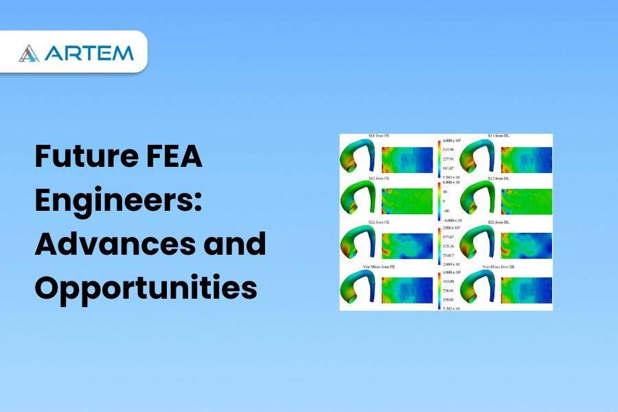
Finite Element Analysis (FEA) has been a powerful tool for engineering simulation for several decades. It has revolutionized the way engineers design and analyze structures, mechanical systems, and other products. However, as technology advances and computational power increases, the future of FEA looks even more promising. In this article, we will explore some of the emerging trends and technologies that are shaping the future of FEA. Artificial Intelligence (AI) and Machine Learning (ML) are revolutionizing the field of Finite Element Analysis (FEA). These technologies bring advanced capabilities and efficiency to FEA simulations. AI and ML techniques enable data-driven material characterization, automating the generation of FEA models, and adapting meshing based on stress distribution. They also facilitate predictive analysis, allowing engineers to forecast system behavior. Furthermore, AI can detect anomalies in simulation results, enhancing safety and reliability. ML-based optimization algorithms aid in design exploration, enabling engineers to efficiently explore design possibilities and find optimal solutions. The integration of AI and ML in FEA holds great potential for improving accuracy, accelerating processes, and driving innovation in engineering analysis. Cloud computing is transforming the field of Finite Element Analysis (FEA) by providing scalable, flexible, and accessible computational resources. With cloud computing, FEA engineers can leverage the power of remote servers and virtual infrastructure to perform complex simulations without the need for extensive local hardware or software installations. One of the key benefits of cloud computing in FEA is the ability to handle large-scale simulations. Cloud platforms offer high-performance computing capabilities, enabling engineers to solve computationally intensive FEA problems in a fraction of the time compared to traditional on-premises setups. This scalability allows for faster turnaround times and increased productivity in analyzing complex systems. Cloud-based FEA also promotes collaboration and remote work. Engineers can easily share simulation models, results, and analysis reports with team members, regardless of their geographical location. This facilitates efficient collaboration, enabling multiple experts to contribute to a project simultaneously and accelerating the overall development process. Another advantage of cloud computing is cost optimization. Instead of investing in expensive hardware and software licenses, FEA engineers can leverage cloud resources on a pay-as-you-go basis. Cloud service providers offer flexible pricing models, allowing users to scale resources up or down based on their specific needs. This approach reduces upfront costs and provides cost-efficiency for FEA projects, as users only pay for the resources they actually use. Furthermore, cloud computing enhances data management and security. Cloud platforms offer robust data storage, backup, and recovery options, ensuring the integrity and availability of FEA models and results. With proper access controls and encryption mechanisms, cloud providers maintain a high level of security, safeguarding sensitive engineering data. Overall, cloud computing revolutionizes FEA by providing on-demand computing power, enabling collaboration, optimizing costs, and enhancing data management and security. It empowers FEA engineers to tackle complex simulations efficiently and accelerates the overall engineering analysis workflow. High-Performance Computing (HPC) plays a crucial role in advancing the capabilities of Finite Element Analysis (FEA) by significantly accelerating the computational performance and enabling complex simulations. HPC refers to the use of powerful computing systems that harness parallel processing and massive data throughput to solve computationally intensive problems. FEA involves solving large systems of equations, which can be time-consuming for traditional computing resources. HPC provides a solution by distributing the workload across multiple processors or nodes, allowing for simultaneous computation and reducing the simulation time. This parallel processing capability empowers FEA engineers to tackle intricate models and perform parametric studies or design optimizations that were previously impractical or unfeasible. HPC also enables the handling of massive datasets involved in FEA simulations. With the ability to process large amounts of data in a shorter time, engineers can perform detailed analyses and capture more accurate results. This is particularly beneficial for simulations involving complex geometries, high mesh densities, or multi-physics phenomena. Additionally, HPC facilitates the exploration of design spaces and optimization in FEA. By leveraging the computational power of HPC clusters, engineers can efficiently evaluate multiple design iterations, perform sensitivity analyses, and conduct optimization studies. This empowers them to identify optimal solutions, enhance product performance, and streamline the design process. Furthermore, HPC allows for the integration of advanced simulation techniques, such as fluid-structure interaction, multi-scale analysis, or coupled physics simulations. These techniques involve complex algorithms and increased computational requirements, which are efficiently handled by HPC systems. This enables engineers to accurately simulate real-world scenarios and capture the interactions between different physical phenomena. In summary, HPC enhances FEA by significantly reducing simulation times, enabling complex simulations, handling large datasets, facilitating design exploration and optimization, and supporting advanced simulation techniques. By leveraging HPC resources, FEA engineers can push the boundaries of analysis capabilities, deliver more accurate results, and accelerate innovation in various fields, including aerospace, automotive, civil engineering, and more. Virtual Reality (VR) and Augmented Reality (AR) are emerging technologies that hold great potential for enhancing the field of Finite Element Analysis (FEA) by providing immersive visualization and interactive experiences. VR enables FEA engineers to step into a virtual environment where they can visualize and explore complex simulations in three dimensions. By wearing a VR headset, engineers can navigate through their FEA models, examine structural deformations, and observe the behavior of simulated systems from different perspectives. This immersive experience aids in understanding the intricate details of the analysis results, identifying potential issues, and gaining valuable insights into the behavior of structures. AR, on the other hand, overlays virtual information onto the real-world environment, allowing FEA engineers to visualize FEA results within their physical surroundings. With the help of AR-enabled devices, engineers can superimpose stress contours, displacement vectors, or other analysis data directly onto physical prototypes or real structures. This integration of virtual and real elements provides a contextual understanding of the FEA results, enabling engineers to compare simulations with physical reality and make more informed decisions. Both VR and AR technologies also facilitate collaborative design and analysis processes. FEA engineers can share their virtual environments or augmented views with team members or stakeholders, enabling them to collectively

Meshing can fail in ANSYS for several reasons, including geometry issues, element quality problems, improper mesh settings, and computational limitations. Here are some common reasons why meshing may fail in ANSYS: 1. Geometry issues refer to problems or anomalies present in the geometry that can hinder the meshing process or cause inaccuracies in the analysis. The issues need to be addressed before attempting to mesh the geometry are: Gaps and overlaps: Gaps occur when there are missing or disconnected surfaces in the geometry, while overlaps happen when surfaces intersect or occupy the same space. Gaps and overlaps prevent the creation of a watertight geometry, which is essential for proper meshing. These issues can result from errors in the CAD model or import process. To resolve them, you need to repair the geometry by closing gaps or removing overlaps using CAD software or Ansys’s geometry tools. Self-intersections: Self-intersections occur when surfaces or bodies intersect or penetrate each other within the geometry. Self-intersections can lead to invalid meshing as the meshing algorithm cannot handle overlapping or intersecting surfaces. It is necessary to identify and resolve self-intersections by modifying or repairing the geometry. Small features or sharp edges: Very small features or sharp edges in the geometry can pose challenges for meshing algorithms. Elements with extremely small sizes can cause meshing failures or lead to poor element quality. In such cases, it may be necessary to simplify or smooth out the geometry by removing unnecessary small details or rounding sharp edges. Thin or sliver surfaces: Thin or sliver surfaces are extremely thin regions in the geometry that can cause meshing difficulties. These surfaces may have a significantly different scale compared to the rest of the model, leading to meshing issues and poor element quality. It is advisable to address thin or sliver surfaces by thickening or removing them if they do not significantly impact the analysis. Complex or poorly defined geometries: Complex geometries with intricate details, sharp corners, or irregular shapes can be challenging to mesh accurately. Poorly defined geometries, lacking proper feature recognition or modeling, can also lead to difficulties in creating a high-quality mesh. In such cases, simplifying or partitioning the geometry and utilizing meshing techniques suitable for complex geometries can help overcome the issues. To address geometry issues: Review and repair the CAD model before importing it into Ansys. Use the geometry repair tools provided in Ansys to fix gaps, overlaps, or self-intersections. Simplify the geometry by removing unnecessary small features or rounding sharp edges. Identify and address thin or sliver surfaces by thickening or removing them if appropriate. Consider partitioning or simplifying complex geometries to facilitate meshing. Collaborate with CAD experts or consult ANSYS documentation and forums for specific guidance on resolving geometry-related issues. By addressing geometry issues, you can ensure a clean and well-defined geometry that facilitates successful meshing and accurate analysis in Ansys. 2. Element quality refers to the measure of the shape and quality of individual elements in a mesh generated in Ansys. High-quality elements are desirable as they ensure accurate and reliable results in finite element analysis. Poor element quality can lead to numerical inaccuracies, convergence difficulties, and unreliable simulation outcomes. Element quality metrics are used to assess the quality of elements within a mesh. Some common element quality metrics include aspect ratio, skewness, orthogonality, and Jacobian. These metrics provide quantitative measures of the element shape and distortion. Evaluate element quality using various tools and methods as mentioned below: Visualization: It provides visualization tools to examine the element quality visually. You can inspect the mesh and identify elements that exhibit poor shapes, such as distorted or highly stretched elements. Visual inspection allows you to identify problematic areas and focus on improving the mesh quality in those regions. Element quality criteria: Allows you to define specific element quality criteria or thresholds. You can set limits for metrics such as aspect ratio, skewness, and Jacobian to identify elements that fall outside the desired range. These criteria help in identifying elements that may adversely affect the accuracy of the analysis. Element quality checks: Ansys includes built-in checks and diagnostics to evaluate element quality. These checks identify problematic elements and provide diagnostic information to help pinpoint issues. For example, the software can flag elements with excessively high skewness or elements with very small aspect ratios. Mesh refinement: If poor element quality is identified in specific areas, you can refine the mesh in those regions. Mesh refinement involves reducing element sizes or employing adaptive meshing techniques to capture more detailed features or resolve distorted elements. Refining the mesh helps to improve element quality and ensures accurate representation of the geometry. By assessing and improving element quality, you can enhance the accuracy and reliability of the finite element analysis conducted. It is essential to maintain a balance between computational efficiency and mesh quality, ensuring that the mesh is fine enough to capture critical features while avoiding excessive computational costs. Inadequate mesh settings : lead to meshing failures or poor-quality meshes, which can adversely affect the accuracy and reliability of the analysis results. It is important to set appropriate meshing parameters to ensure a well-behaved and suitable mesh for the intended analysis. Here are some common inadequate mesh settings and their implications. Element size: The element size determines the level of mesh detail and accuracy. Inadequate element size settings can result in either a mesh that is too coarse, failing to capture important features and variations in the geometry, or a mesh that is too fine, leading to excessive computational costs. It is crucial to select an appropriate element size based on the geometry, analysis requirements, and the desired balance between accuracy and computational efficiency. Growth rate: The growth rate specifies how the element size increases or decreases as you move away from specified regions or boundaries. Inadequate growth rate settings can lead to abrupt transitions in element sizes or a lack of smooth gradation in the mesh. It is important to choose a suitable growth rate that ensures a smooth