Geometry clean-up is of utmost importance in the field of computer-aided design (CAD) as it ensures the accuracy, efficiency, and reliability of the models created. Cleaning up the geometry involves removing errors, inconsistencies, and unnecessary complexity from the CAD model. By doing so, engineers and designers can have confidence in the accuracy of their designs, leading to better outcomes in various applications.
One key importance of geometry clean-up is its impact on design accuracy. Clean geometry ensures that the CAD model faithfully represents the intended design, free from errors and gaps that could compromise its integrity. This accuracy is crucial for precise measurements, analysis, and simulation, as well as effective communication with stakeholders.
Here are some general steps to perform geometry clean-up in CAD:
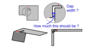
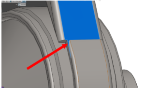
Identify Issues: Carefully examine the model to identify any geometric issues, such as gaps, overlaps, self-intersections, duplicate entities, or small sliver surfaces. Use visualization tools and analysis features in your CAD software to aid in identifying problematic areas.
Gap and Overlap Removal: Address any gaps or overlaps between entities by using appropriate CAD tools. This may involve adjusting dimensions, extending or trimming entities, or using commands like filleting or chamfering to blend and connect surfaces or edges.
Remove Duplicate Geometry: Identify and delete any duplicate entities such as lines, curves, or surfaces. These duplicates can cause issues during subsequent operations or analyses.
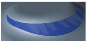
Healing and Repairing Surfaces: If the model contains surface imperfections or errors, use CAD tools for surface healing and repairing. These tools can analyze and fix issues like self-intersecting surfaces, non-manifold edges, or irregularities in surface normal.
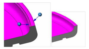
Correct Small Edges and Faces: Identify and delete small edges or faces that might result from numerical inaccuracies or errors during the modeling process. These small entities can cause problems during meshing or further processing.
Simplify Complex Geometry: Analyze the model for complex or intricate details that are not essential for the desired outcome. Simplify or remove unnecessary features to reduce model complexity and improve computational efficiency.
Merge Coincident Entities: Identify entities that are coincident or very close to each other and merge them into a single entity. This process helps eliminate redundant entities and improves the model’s clarity and simplicity.

Remove Duplicates: Identify and eliminate duplicate or redundant entities such as points, lines, or surfaces. Use CAD commands like merge, join, or remove duplicates to consolidate the model and reduce unnecessary complexity.
Check and Correct Normals: Verify that the normals (direction vectors perpendicular to the surface) of the model’s faces are consistent and pointing in the desired direction. Inconsistent or inverted normals can cause issues in rendering, analysis, or manufacturing processes.
Repair Self-Intersections: Detect and resolve any self-intersections within the model, where surfaces or solid bodies intersect with themselves. These intersections can cause problems during simulation or manufacturing, and need to be resolved.
Edge and Face Cleanup: Inspect the model for inconsistent or unnecessary edges or faces. Delete or merge redundant edges, remove unwanted internal features, and ensure smooth and continuous surfaces.
Feature Verification: Validate important geometric features and dimensions to ensure they meet design requirements. Use measurement and analysis tools in your CAD software to verify dimensions, tolerances, angles, and other critical features.
Optimize Topology: Analyze the model’s topology and rework it if necessary to improve efficiency, accuracy, or performance. This step involves assessing the connectivity and arrangement of the model’s components and modifying them as needed.
Validate Model Integrity: Use built-in CAD tools or specialized software to perform integrity checks on the model, looking for errors such as open edges, non-manifold geometry, or invalid entities. Address any identified issues to ensure a clean and error-free model.
Document the Cleaning Process: Keep a record of the cleaning steps performed on the CAD model, including any modifications or repairs made. This documentation aids in maintaining traceability and provides a reference for future modifications or troubleshooting.
By following these steps, engineers and designers can ensure that the CAD geometry is clean, accurate, and ready for further operations such as analysis, simulation, or manufacturing.
Simulation and Analysis Accuracy: Accurate geometry is crucial for reliable simulation and analysis results. Any inaccuracies or inconsistencies in the geometry can propagate and affect the accuracy of simulations or analyses. Cleaning up the geometry ensures that the model provides a solid foundation for obtaining accurate results.
Manufacturing Readiness: Clean geometry is essential for manufacturing processes. When transferring the CAD model to manufacturing software or physical production, clean geometry ensures that the design is ready for manufacturing. It reduces the likelihood of errors, such as misinterpretations or difficulties in translating the design into a physical product.
Collaboration and Communication: Clean geometry facilitates effective collaboration and communication among team members and stakeholders. It improves the clarity of the design, making it easier to understand and review. Clean geometry helps ensure that everyone involved in the project has a clear and accurate representation of the design intent.
Data Interoperability: Clean geometry enhances data interoperability between different CAD systems and engineering tools. When sharing or exchanging CAD models, clean geometry reduces the chances of data loss or compatibility issues. It ensures that the model can be seamlessly integrated into different workflows and software environments.
In summary, cleaning up CAD geometry is essential to ensure design accuracy, optimize modeling efficiency, avoid errors, obtain accurate simulation results, prepare for manufacturing, facilitate collaboration, and enable data interoperability. It plays a critical role in maintaining the integrity and reliability of the design throughout the entire product development process.
As mentioned, clean-up geometry plays a significant role in manufacturing readiness. It ensures that the CAD model can be seamlessly translated into physical production, reducing the risk of errors or difficulties in manufacturing processes such as machining or 3D printing. Clean geometry promotes smooth data transfer and compatibility, contributing to efficient and high-quality manufacturing outcomes.
If you’re interested in improving your CAD skills and learning more about geometry clean-up, you may consider exploring CAD courses such as NX Semens, Solidworks, CATIA and so on. One notable online platform that offers CAD courses is Artem Academy. They provide a variety of online courses and tutorials aimed at enhancing your CAD proficiency and knowledge. By enrolling in these courses, you can gain a deeper understanding of geometry clean-up techniques, which can be essential for maintaining design accuracy, optimizing efficiency, improving analysis and simulation reliability, and facilitating manufacturing readiness. These courses can also help you enhance the overall quality of your CAD models, enabling you to achieve better results in various applications.