Element quality refers to the measure of how well an element represents the physical shape or behavior of the structure or system being analyzed. It provides an indication of the accuracy and reliability of the numerical results obtained from the finite element analysis (FEA).
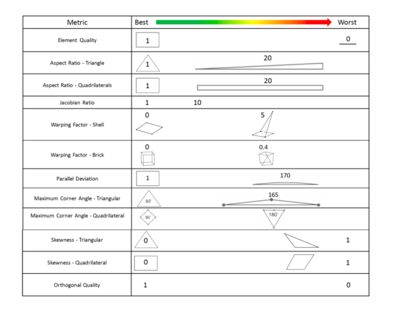
ANSYS uses various metrics to evaluate the element quality. Some commonly used measures include:
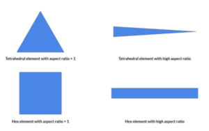
Aspect ratio refers to the ratio of the longest edge or element size to the shortest edge or element size within a finite element mesh. It is used as a measure of the geometric quality of the mesh elements and can impact the accuracy and reliability of the analysis results.
Aspect ratio is typically used as an indicator of mesh distortion or element shape irregularity. Ideally, elements in a mesh should have a reasonably uniform size and shape to accurately represent the geometry and avoid numerical issues. Mesh elements with poor aspect ratios can lead to numerical instability, inaccurate results, and difficulties in convergence during the analysis.
The limits for acceptable aspect ratios depend on the type of elements being used and the specific analysis requirements. Here are some general guidelines:
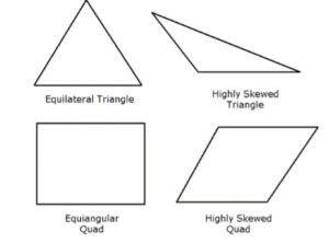
1. Triangular Elements: For triangular elements, a commonly used quality measure is the ratio of the longest edge to the shortest edge. An aspect ratio close to 1 indicates nearly equilateral triangles, which are desirable for accuracy. In practice, aspect ratios up to 5 or 6 are often considered acceptable, but it is generally recommended to keep aspect ratios below 3 for well-conditioned elements.
2. Quadrilateral Elements: For quadrilateral elements, aspect ratio is defined as the ratio of the longest side to the shortest side. Similar to triangular elements, it is desirable to have nearly square or rectangular elements with aspect ratios close to 1. Acceptable limits for aspect ratios of quadrilateral elements typically range from 1 to 4 or 5, depending on the specific analysis and element type.
It’s important to note that these aspect ratio limits are general guidelines and may vary depending on the specific analysis requirements, element type, and the software being used. In some cases, higher aspect ratios may be tolerated if they do not significantly affect the accuracy or stability of the analysis.
In addition to aspect ratio, there are other mesh quality measures, such as element skewness, angle distortion, and element size variation, which should also be considered in assessing the overall mesh quality. Proper mesh refinement and optimization techniques can be employed to improve element quality and achieve a well-conditioned mesh for accurate and reliable finite element analysis.
Warpage, also known as element distortion or element skewness, is a measure of the deviation from the ideal shape of a finite element. It quantifies the non-planarity or non-straightness of the element faces or edges. Warpage can affect the accuracy and convergence of finite element analysis results and is often considered in element quality checks.
The warpage limit is a criterion that defines the maximum allowable warpage for an element to be considered acceptable. If an element exceeds the warpage limit, it is considered distorted and may lead to inaccurate or unreliable analysis results.
The warpage limit is typically expressed as a dimensionless value or a percentage of the element size. The specific warpage limit depends on the element type, the analysis requirements, and the software being used. However, in general, a common guideline for triangular or quadrilateral elements is to keep the warpage below 0.2 or 20%. This means that the maximum deviation from the ideal shape should not exceed 20% of the element size.
It’s important to note that the warpage limit is just one aspect of element quality checks, and other measures, such as aspect ratio, angle distortion, and element size variation, should also be considered. In practice, it is recommended to use a combination of quality measures to evaluate the overall quality of the mesh and ensure accurate and reliable analysis results.
If elements exceed the warpage limit, mesh refinement techniques, such as element splitting or repositioning, can be applied to improve the element quality. Additionally, using higher-order elements or alternative element types may help reduce warpage and improve the accuracy of the analysis.
Overall, maintaining low warpage within acceptable limits is important to ensure good element quality and reliable results in finite element analysis.
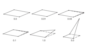
Parallel deviation, also known as skewness or shape deviation, is a measure of how well the faces or edges of a finite element align with the ideal geometric shape. It quantifies the deviation from the ideal straightness or parallelism of the element edges or faces. Parallel deviation is an important aspect of element quality checks and can impact the accuracy and convergence of finite element analysis.
The parallel deviation limit is a criterion that defines the maximum allowable deviation from parallelism for an element to be considered acceptable. If an element exceeds the parallel deviation limit, it is considered distorted, and it may introduce errors or instability in the analysis results.
The parallel deviation limit is typically expressed as a dimensionless value or a percentage. The specific limit depends on the element type, the analysis requirements, and the software being used. However, a common guideline for triangular or quadrilateral elements is to keep the parallel deviation below 0.2 or 20%. This means that the maximum deviation from parallelism should not exceed 20% of the element size.
It’s important to note that the parallel deviation limit is just one aspect of element quality checks, and other measures, such as aspect ratio, warpage, and element size variation, should also be considered. Evaluating multiple quality measures provides a comprehensive assessment of the mesh quality and ensures accurate and reliable analysis results.
If elements exceed the parallel deviation limit, techniques such as element repositioning, mesh smoothing, or mesh refinement can be employed to improve the element quality. Additionally, using higher-order elements or alternative element types with better shape control can help reduce parallel deviation and improve the accuracy of the analysis.
In summary, maintaining low parallel deviation within acceptable limits is crucial for good element quality and reliable finite element analysis. It helps ensure proper alignment and parallelism of element edges or faces, which is important for accurate stress and deformation calculations.
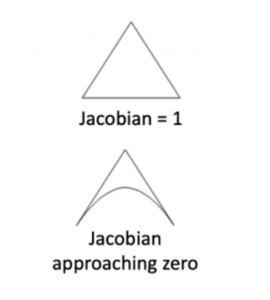
The Jacobian is a measure of the distortion or deformation of an element resulting from the mapping between its reference configuration (often defined as the “natural” or “deformed” shape) and its current configuration under applied loads. The Jacobian is used to assess the element’s shape and distortion, and it plays a significant role in element quality checks.
The Jacobian matrix represents the derivative of the transformation between the reference and current configurations. It describes the local stretching, shearing, and rotation of the element. The Jacobian matrix is typically computed using the partial derivatives of the shape functions that define the element and the nodal coordinates.
The determinant of the Jacobian matrix, denoted as J or det(J), is commonly used as a measure of element distortion. It represents the volume change or scaling factor associated with the element deformation. A positive Jacobian indicates proper element orientation, while a negative Jacobian indicates an inverted or self-intersecting element.
The limits for the Jacobian determinant depend on the specific element type and analysis requirements. However, in general, the Jacobian determinant should be strictly positive and preferably close to unity (i.e., det(J) > 0 and det(J) ≈ 1) for well-conditioned elements. This ensures proper element shapes, avoids element inversions or self-intersections, and helps maintain the accuracy and stability of the analysis.
If the Jacobian determinant is significantly different from unity or becomes negative, it indicates severe element distortion, and the element may need to be remeshed or refined. Element quality checks often include criteria based on the Jacobian determinant to identify distorted or poorly shaped elements.
In some FEA software, additional measures, such as the minimum Jacobian ratio or the condition number, are used to assess element distortion and quality. These measures provide further information about the element’s deformation and help identify elements with high distortion or poor geometric fidelity.
It’s important to note that the specific limits for the Jacobian determinant depend on the element type, analysis requirements, and the software being used. Consulting the FEA software documentation or established guidelines specific to the element type and analysis domain can provide more detailed information regarding the acceptable limits for the Jacobian determinant in element quality checks.
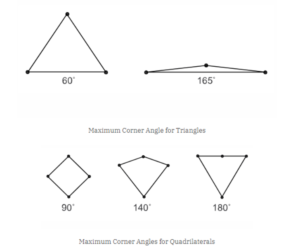
In element quality checks, maximum and minimum values are used to evaluate various measures of element quality. These values help identify elements that deviate significantly from desired criteria and may indicate potential issues with the mesh or analysis. The specific maximum and minimum limits vary depending on the type of measure being considered and the specific analysis requirements.
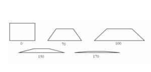
Here are the maximum and minimum limits commonly considered for element angles:
1. Maximum Angle:
• For triangular elements: The maximum angle within a triangular element should generally be less than 180 degrees. An upper limit of around 170 degrees is often used to ensure that the element does not become excessively elongated or distorted.
• For quadrilateral elements: The maximum angle within a quadrilateral element should be less than 180 degrees as well. Typically, an upper limit of around 170 degrees is employed to maintain a reasonably regular shape.
2. Minimum Angle:
• For triangular elements: The minimum angle within a triangular element should be greater than zero. A lower limit of around 10-15 degrees is often set to avoid highly acute angles, which can lead to numerical instability and inaccurate results.
• For quadrilateral elements: The minimum angle within a quadrilateral element should also be greater than zero. A lower limit of around 10-15 degrees is generally used to prevent highly distorted or skewed shapes.
It’s important to note that these maximum and minimum limits for element angles are general guidelines and may vary depending on the specific element type, analysis requirements, and software being used. The precise limits may be influenced by factors such as the material properties, element formulation, and specific analysis conditions.
In practice, element quality checks consider a combination of measures, including aspect ratio, warpage, parallel deviation, and angle deviation, to assess the overall quality of the mesh. Ensuring that element angles are within acceptable limits helps maintain mesh regularity, accuracy, and stability during finite element analysis.
Skewness, also known as skew, is a measure of the distortion or misalignment of an element’s shape compared to an ideal or regular shape. In the context of element quality checks in finite element analysis (FEA), skewness is used to evaluate the non-planarity or non-orthogonality of an element’s faces or edges.
Skewness is typically assessed by measuring the angle between the element’s faces or edges and comparing them to their ideal angles. A highly skewed element indicates a significant deviation from the desired shape, which can affect the accuracy and convergence of the analysis results.
The limits for acceptable skewness depend on the specific element type and analysis requirements. However, in general, a commonly used guideline is to keep the skewness angle below 30 degrees or even below 15 degrees for well-conditioned elements. This means that the deviation from the ideal angle should be minimal, and the element’s faces or edges should be as close to perpendicular or parallel as possible.
It’s important to note that the specific limits for skewness may vary depending on the element type, analysis requirements, and the software being used. Additionally, different guidelines or standards may exist in specific industries or applications.
If elements exceed the skewness limits, it may be necessary to improve the element quality through mesh refinement, element repositioning, or utilizing alternative element types that better accommodate the geometry or loading conditions.
Skewness is one of several quality measures used in element quality checks, alongside measures such as aspect ratio, warpage, parallel deviation, and angle deviation. Assessing multiple quality measures provides a comprehensive evaluation of the mesh and helps ensure accurate and reliable finite element analysis results.
The quality of these elements plays a crucial role in the accuracy and reliability of the simulation results. It is important to note that the specific element quality criteria may vary depending on the type of analysis and the element type being used (such as 2D elements, 3D elements, etc.).
By this we understood that, the term “element quality” refers to the measure of how well an element represents the physical behavior of the structure being analyzed. A high-quality element accurately captures the deformation and stress distribution, while a poor-quality element may introduce errors and lead to inaccurate results. The specific criteria for element quality can vary depending on the type of analysis being performed and the type of elements used.
To evaluate and visualize element quality, FEA software provides tools and functions that calculate these quality metrics for each element in the mesh. Engineers can use these tools to identify problematic elements that may lead to numerical instabilities or inaccurate results. Visualizing element quality can help pinpoint areas where improvements are needed, such as refining the mesh or adjusting the element type.
By improving the quality of elements in a finite element model, engineers can enhance the accuracy and reliability of the simulation results. It allows for better representation of the physical behavior of the system being analyzed and ensures that the FEA solution provides valuable insights for design optimization, performance evaluation, and structural analysis.
For individuals interested in enhancing their skills in Finite Element Analysis (FEA) and Computer-Aided Engineering (CAE) through training courses by Artem Academy. Some popular FEA software packages, such as ANSYS course in India, Hyper mesh, and Ansys Workbench, offer comprehensive training programs and certifications. These courses, like the one provided by Artem, can help individuals gain expertise in FEA methodologies, element types, meshing techniques, and result interpretation, empowering them to effectively apply FEA in engineering and scientific domains.