

Introduction: In the intricate world of engineering and design, understanding how heat is distributed and managed within structures is paramount. Steady-State Thermal Analysis stands as a powerful tool in this quest, providing engineers with invaluable insights into temperature distributions, heat flow patterns, and the thermal equilibrium of a system. In this blog, we’ll delve into the principles, applications, and benefits of Steady-State Thermal Analysis. The Fundamentals of Steady-State Thermal Analysis: 1.Steady-State vs. Transient Analysis: Steady-State Analysis: In steady-state conditions, temperatures, and heat distributions within a system remain constant over time. This analysis assumes that the system has reached thermal equilibrium, allowing engineers to focus on the long-term behavior of the structure. Transient Analysis: In contrast, transient analysis considers changes in temperature over time, exploring how the system responds to dynamic heat inputs or varying thermal conditions. 2.Governing Equations: The fundamental equation governing steady-state thermal analysis is the heat conduction equation: ∇⋅(k∇T)+Q=0 Where k is the thermal conductivity, T is the temperature, and Q represents any heat sources or sinks. Conducting Steady-State Thermal Analysis: 1.Boundary Conditions: Setting appropriate boundary conditions is crucial. Engineers define temperatures, heat fluxes, or convective heat transfer coefficients at different surfaces to simulate real-world scenarios. 2.Material Properties: Accurate representation of material properties, especially thermal conductivity, is essential. Different materials conduct heat at varying rates, impacting how heat is transferred within the structure. 3.Mesh Generation: Discretizing the structure into smaller elements through mesh generation is a key step. A finer mesh allows for a more accurate representation of temperature variations. 4.Solver Selection: Solvers, often finite element analysis (FEA) tools, are employed to solve the complex mathematical equations governing heat transfer. These tools provide temperature distributions and heat fluxes within the structure. Applications of Steady-State Thermal Analysis: 1.Electronics Cooling: Ensuring electronic components operate within temperature limits is critical. Steady-state thermal analysis helps optimize heat sink designs and cooling strategies. 2.Building Thermal Performance: Evaluating how heat is transferred through building materials aids in designing energy-efficient structures. This analysis is crucial for assessing insulation requirements and HVAC system sizing. 3.Automotive Engineering: In the automotive industry, steady-state thermal analysis is employed to prevent overheating of components, optimize radiator designs, and enhance overall vehicle thermal performance. 4.Industrial Equipment: Efficient operation of industrial machinery often relies on steady-state thermal analysis to prevent overheating and optimize heat dissipation mechanisms. Benefits of Steady-State Thermal Analysis: 1.Optimization of Designs: Engineers can fine-tune designs to ensure that components operate within temperature limits, maximizing efficiency and longevity. 2.Cost Savings: By identifying potential overheating issues early in the design process, unnecessary costs associated with redesign and system failures can be avoided. 3.Energy Efficiency: Steady-state thermal analysis contributes to the development of energy-efficient systems by optimizing insulation, cooling, and heating strategies. Conclusion: Steady-state thermal analysis is an indispensable tool for engineers navigating the complex world of heat transfer. From electronics to buildings and industrial machinery, the insights gained from this analysis play a pivotal role in optimizing designs, ensuring reliability, and fostering innovation in diverse engineering domains. As technology advances, the application of steady-state thermal analysis continues to shape the way we harness and manage heat in the pursuit of safer, more efficient, and resilient systems.
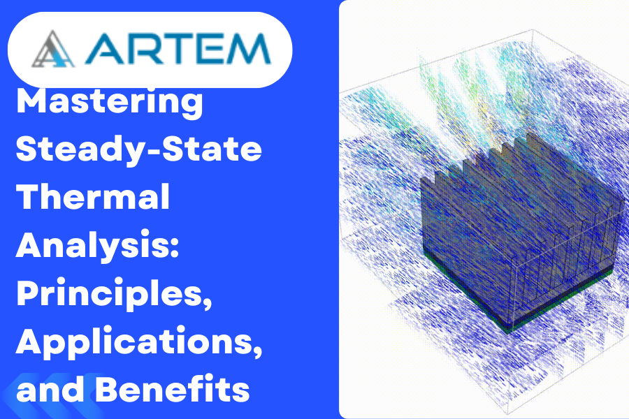
Introduction: In the intricate world of engineering and design, understanding how heat is distributed and managed within structures is paramount. Steady-State Thermal Analysis stands as a powerful tool in this quest, providing engineers with invaluable insights into temperature distributions, heat flow patterns, and the thermal equilibrium of a system. In this blog, we’ll delve into the principles, applications, and benefits of Steady-State Thermal Analysis. 1. Steady State Analysis: In steady-state conditions, temperatures, and heat distributions within a system remain constant over time. This analysis assumes that the system has reached thermal equilibrium, allowing engineers to focus on the long-term behavior of the structure 2. Transient Analysis: In contrast, transient analysis considers changes in temperature over time, exploring how the system responds to dynamic heat inputs or varying thermal conditions. Governing Equations: The fundamental equation governing steady-state thermal analysis is the heat conduction equation: $$\nabla⋅(\nabla)+=0\nabla⋅(k\nabla T)+Q=0$$ Where k is the thermal conductivity, T is the temperature, and Q represents any heat sources or sinks. Conducting Steady-State Thermal Analysis: $$a^2\;+\;b^{2\;}=\;KU$$ Boundary Conditions: Setting appropriate boundary conditions is crucial. Engineers define temperatures, heat fluxes, or convective heat transfer coefficients at different surfaces to simulate real-world scenarios. Material Properties: Accurate representation of material properties, especially thermal conductivity, is essential. Different materials conduct heat at varying rates, impacting how heat is transferred within the structure. Mesh Generation: Discretizing the structure into smaller elements through mesh generation is a key step. A finer mesh allows for a more accurate representation of temperature variations. Solver Selection: Solvers, often finite element analysis (FEA) tools, are employed to solve the complex mathematical equations governing heat transfer. These tools provide temperature distributions and heat fluxes within the structure. Applications of Steady-State Thermal Analysis: 1. Electronics Cooling: Ensuring electronic components operate within temperature limits is critical. Steady-state thermal analysis helps optimize heat sink designs and cooling strategies. 2. Building Thermal Performance: Evaluating how heat is transferred through building materials aids in designing energy-efficient structures. This analysis is crucial for assessing insulation requirements and HVAC system sizing. 3. Automotive Engineering: In the automotive industry, steady-state thermal analysis is employed to prevent overheating of components, optimize radiator designs, and enhance overall vehicle thermal performance. 4. Industrial Equipment: Efficient operation of industrial machinery often relies on steady-state thermal analysis to prevent overheating and optimize heat dissipation mechanisms. Benefits of Steady-State Thermal Analysis: 1. Optimization of Designs: Engineers can fine-tune designs to ensure that components operate within temperature limits, maximizing efficiency and longevity. 2. Cost Savings: By identifying potential overheating issues early in the design process, unnecessary costs associated with redesign and system failures can be avoided. 3. Energy Efficiency: Steady-state thermal analysis contributes to the development of energy-efficient systems by optimizing insulation, cooling, and heating strategies. Conclusion: Steady-state thermal analysis is an indispensable tool for engineers navigating the complex world of heat transfer. From electronics to buildings and industrial machinery, the insights gained from this analysis play a pivotal role in optimizing designs, ensuring reliability, and fostering innovation in diverse engineering domains. As technology advances, the application of steady-state thermal analysis continues to shape the way we harness and manage heat in the pursuit of safer, more efficient, and resilient systems.
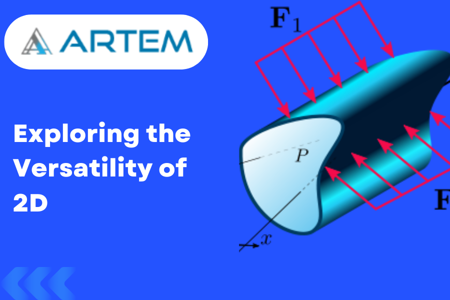
In Finite Element Analysis, the continuous domain is divided into a mesh of smaller subregions called elements, and each element is represented by a mathematical approximation referred to as a finite element. These elements are typically classified as one-dimensional (1D), two-dimensional (2D), or three-dimensional (3D), depending on the dimensionality of the problem being modeled. Specifically, 2D finite elements are used to discretize problems that exhibit behavior primarily in two dimensions, such as plane stress, plane strain, or axisymmetric problems. They are employed when the geometry and loading conditions can be adequately represented in a two-dimensional plane, and the third dimension can be neglected or approximated as a constant value. The shape and formulation of 2D finite elements can vary depending on the specific problem being addressed. Common types of 2D elements include triangular elements (e.g., linear or quadratic triangles) and quadrilateral elements (e.g., bilinear or biquadratic quadrilaterals). These elements are defined by a set of nodes and interpolation functions that approximate the behavior of the underlying continuous domain. The behavior of the structure or system can be analyzed, and quantities such as displacements, stresses, strains, and other relevant variables can be evaluated at specific points within each element. Overall, 2D elements in FEM provide a powerful numerical tool for analyzing and simulating the behavior of structures and systems in two-dimensional space, enabling engineers and researchers to gain insights into the mechanical response of various physical phenomena. Here is a detailed explanation of common types of 2D elements: 2D plane stress 2D plane stress refers to a simplified modeling approach used to analyze the behavior of a thin structure or component. It assumes that the stresses and strains within the structure are primarily confined to a single plane, neglecting the effects of stress and strain variations in the thickness direction. When considering the thickness element in a 2D plane stress analysis, it is assumed that the thickness of the structure is much smaller compared to its other dimensions. This assumption allows for the simplification of the analysis by reducing the problem from a 3D scenario to a 2D plane, where stress and strain components vary only within that plane. In this analysis, the structure is typically represented by a flat, two-dimensional model. The stresses and strains are assumed to vary only in the X and Y directions, while remaining constant in the Z (thickness) direction. This simplification allows for the application of two-dimensional equations of equilibrium and constitutive laws to determine the stresses, strains, and deformations within the structure. It is important to note that the 2D plane stress analysis is applicable only when the effects of stress variations in the thickness direction can be reasonably neglected. Overall, the 2D plane stress analysis with thickness element provides a simplified approach to analyze thin structures, allowing for efficient and practical analysis while capturing the essential behavior of the system within the plane of interest. 2D plane strain 2D plane strain element is a modeling approach used to analyze the behavior of a structure or component subjected to deformation in two dimensions while assuming no strain variations in the third dimension. It is typically employed when the structure or component is much larger in the third dimension compared to its thickness or other dimensions. The deformation and resulting strains within the structure are assumed to be primarily confined to a single plane, while negligible in the direction perpendicular to that plane. This assumption allows for simplification of the analysis by reducing the problem from a 3D scenario to a 2D plane, where strains vary only in the X and Y directions. The structure or component is typically represented by a two-dimensional model, where deformations and strains occur in the X and Y directions. The analysis involves applying two-dimensional equations of equilibrium and constitutive laws to determine the stresses, strains, and deformations within the structure. It is important to note that the 2D plane strain analysis is suitable when the strains in the direction perpendicular to the plane of interest are relatively small or negligible. This assumption is valid for structures or components that are significantly larger in one dimension compared to the other two dimensions, such as long beams, thick plates, or deep foundations. However, it is crucial to carefully consider the suitability of the 2D plane strain assumption for a given problem. If significant strain variations occur in the out-of-plane direction, a more comprehensive three-dimensional analysis may be necessary to accurately capture the behavior of the structure. In summary, a 2D plane strain element is a modeling technique used to analyze structures or components subjected to deformation in two dimensions while neglecting strain variations in the third dimension. It provides a practical and efficient approach for analyzing systems with predominant deformation occurring in a single plane. 2D Axi-Symmetric 2D axisymmetric element is a modeling approach used to analyze the behavior of a structure or component that possesses rotational symmetry around a central axis. It is particularly suitable for studying cylindrical or rotationally symmetric geometries, such as pipes, pressure vessels, or circular plates. In a 2D axisymmetric analysis, the deformation and resulting strains within the structure are assumed to be axisymmetric, meaning they vary only in the radial and axial directions. This assumption allows for a simplification of the analysis by reducing the problem from a 3D scenario to a 2D axisymmetric plane, eliminating the need to model the entire 3D volume. The structure or component is typically represented by a 2D axisymmetric model, where deformations, strains, and stresses are computed for points along the radial and axial directions. The analysis involves applying axisymmetric equilibrium equations and constitutive laws to determine the stresses, strains, and deformations within the structure. The boundary conditions applied to the model are also axisymmetric, and the loading conditions are assumed to be symmetrical about the central axis. This allows for the consideration of rotational symmetry and simplifies the analysis process. It is important to note that the 2D axisymmetric analysis is suitable when the geometry and

In modal analysis, mode shapes and nodal diameters are essential concepts that provide valuable insights into the dynamic behavior of structures. Let’s delve into each term and understand their significance, along with the corresponding formulas. Mode Shapes: Definition: Mode shapes represent the spatial distribution of displacements within a structure at a specific natural frequency. They illustrate how different parts of the structure move relative to each other during vibration. Formula: For a structure with n degrees of freedom, the mode shape is represented by a vector U, where each element Ui denotes the displacement at the i-th degree of freedom. The mode shape is obtained by solving the eigenvalue problem: $$=2KU=\omega2MU$$ K is the stiffness matrix, M is the mass matrix, ω is the circular frequency (related to the natural frequency by =2 ω=2πf), U is the mode shape vector. In practical terms, once the eigenvalues and eigenvectors are obtained, the mode shapes are extracted from the eigenvectors. Nodal Diameters: Definition: Nodal diameters are regions within a mode shape where the displacement is zero. These nodal diameters correspond to points of minimal or no movement during vibration. Formula: The nodal diameters can be understood through the mode shape vector U. The positions where the elements of U are zero represent nodal points or lines. For a given mode shape, the nodal diameters are essentially the areas or lines of the structure where no motion occurs. For a 1D structure (e.g., a beam), a nodal diameter might be a point where the displacement is zero. For a 2D structure (e.g., a plate), nodal diameters could be lines or curves where the displacement is zero. In 3D structures, nodal volumes may exist. Significance: Mode Shapes: Understanding mode shapes is crucial for engineers as they provide a visual representation of how a structure deforms during vibration. This insight is essential for optimizing designs, identifying potential weaknesses, and ensuring that the structure can withstand dynamic loads without encountering resonance issues. Nodal Diameters: Identifying nodal diameters helps engineers pinpoint regions in a structure where minimal or no movement occurs during vibration. This information is valuable for design optimization, allowing engineers to reinforce or modify specific areas to enhance structural performance. In summary, mode shapes and nodal diameters play pivotal roles in modal analysis, offering engineers a deeper understanding of the dynamic response of structures and aiding in the design and optimization processes.
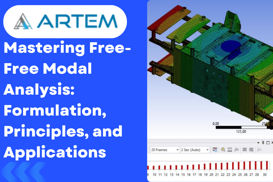
In the realm of structural engineering, the quest for understanding the dynamic behavior of systems has led to the development of sophisticated analysis techniques. One such powerful method is Free-Free Modal Analysis, a process that goes beyond conventional modal analysis by considering structures that are unrestrained at their boundaries. In this blog, we’ll explore the formulation behind Free-Free Modal Analysis, unlocking the secrets to finding natural frequencies and mode shapes. Understanding the Basics: Before delving into the formulation, let’s grasp the fundamental principles governing Free-Free Modal Analysis: Unrestrained Boundaries: Unlike traditional modal analysis, Free-Free Modal Analysis assumes that the structure is not fixed or constrained at its boundaries. This is a crucial departure from other modal analysis methods, as it allows for a more accurate representation of the dynamic behavior of the system. Natural Frequencies: The primary objective of this analysis is to determine the natural frequencies of the structure. These frequencies represent the inherent vibrational modes of the system and are critical for understanding how it responds to dynamic loads. Mode Shapes: Mode shapes describe the spatial distribution of deformations within the structure during vibration. Identifying mode shapes is essential for gaining insights into the dynamic response and potential weaknesses of the system. Formulation of Free-Free Modal Analysis: The formulation for Free-Free Modal Analysis involves solving the equations of motion for the structure. The basic equation of motion for a single-degree-of-freedom system can be expressed as: M is the mass matrix, C is the damping matrix, K is the stiffness matrix, u is the displacement vector, ¨u¨ is the acceleration vector, ˙u˙ is the velocity vector, and F is the force vector. For a structure with multiple degrees of freedom, the equation of motion becomes a set of coupled second-order differential equations, typically represented in matrix form as: $$M\ddot U+\;C\dot U+\;KU\;=F$$ where U is the vector of displacements for all degrees of freedom. To find the natural frequencies and mode shapes, one needs to solve the eigenvalue problem: $$2KU=\omega2MU$$ Here, ω represents the circular frequency, and U is the eigenvector associated with each natural frequency. Once the natural frequencies (ω) are obtained, the corresponding mode shapes can be extracted from the eigenvectors U. These mode shapes depict the spatial distribution of deformations during vibration. Applications and Benefits: Aerospace Industry: Free-Free Modal Analysis aids in optimizing the design of aircraft and spacecraft, ensuring that the structures can withstand dynamic loads encountered during flight. Automotive Engineering: In the automotive sector, this analysis technique is employed to enhance vehicle safety, comfort, and overall performance by identifying and addressing potential vibration issues. Civil Engineering: Free-Free Modal Analysis plays a crucial role in designing resilient structures such as bridges and buildings, helping engineers understand and mitigate the impact of dynamic forces like wind and earthquakes. Conclusion: Free-Free Modal Analysis, with its sophisticated formulation, stands as a cornerstone in unraveling the complexities of structural dynamics. Armed with the ability to determine natural frequencies and mode shapes, engineers can optimize designs and ensure the robustness of structures across various industries. As technology advances, the integration of such analytical tools continues to shape the future of structural engineering, offering unprecedented insights for safer and more efficient designs.

The introduction of new technology often has a significant impact on society and the economy, as it can drive innovation, improve productivity, and create new markets and jobs. New technology can also improve the quality of life for individuals and communities by addressing social and environmental challenges, such as healthcare, education, and climate change. Mechanical engineering has made some of these expectations a reality. By which many smart machines have been invented that make our lives easier. These machines are engineered using applications such as Ansys. It is a software suite that engineers can use to design revolutionary projects. Ansys Story For more than 50 years, Ansys engineering simulation software has enabled innovators across industries to push boundaries using the predictive power of simulation. The next great leaps in human advancement will be powered by Ansys. Founded in 1970, Ansys is the original and gold standard simulation provider. Also Read: Need to add another blog title and link to other blog Simulation is All Ansys Does Ansys 4,900 global associates are singularly focused on giving engineers the clarity and confidence to simulate their way towards transformational innovation. #1 in engineering simulation Best-of-breed portfolio across all physics High-fidelity results Best-in-class technical support The Superpower to Engineer What’s Ahead Ansys simulation gives engineers the ability to explore and predict how products will work — or won’t work — in the real world. It’s like being able to see the future, enabling engineers to innovate as never before. This simulation superpower also speeds time-to-market, lowers manufacturing costs, improves quality and decreases risk. Improved operational efficiency Higher engineering productivity Reduced warranty reserves Streamlined regulatory approvals Fewer physical prototypes More products with same resources Why should you study Ansys? As a mechanical engineer looking to specialize in structural design, you need to learn as much relevant software as you can. Every company has its own strategies to reduce testing costs, and Ansys is fast becoming a popular choice. Aside from the cost advantages, Ansys is also known for its simulation programs. Each has a specific function to produce accurate test results. The software effectively combines mechanical engineering and physics. Taking an Ansys training course will put you at an advantage when it comes to future employment. It takes serious commitment to understand how to make use of the software. As long as you have a good theoretical background in engineering, then you are good to go. Also Read: Need to add another blog title and link to other blog In simple words, here some reasons mentioned are: 1.Career opportunities: ANSYS is widely used in various industries, including aerospace, automotive, defense, energy, and healthcare. Having knowledge of ANSYS can make you highly desirable to employers in these industries. 2.Improved design skills: ANSYS can help you develop a better understanding of how products and processes behave under different conditions. This can lead to improved design skills and the ability to create more efficient and effective products. 3.Reduced costs: By using ANSYS to simulate and test products, you can reduce the need for physical testing and prototyping. This can save time and money, as well as reduce the environmental impact of product development. 4.Enhanced problem-solving abilities: ANSYS can help you develop critical thinking and problem-solving skills. By analyzing and interpreting simulation results, you can gain insights into the behavior of complex systems and develop effective solutions to engineering problems. 5.Access to a community of experts: ANSYS has a large and active user community, which can provide support, advice, and inspiration for your engineering projects. Studying ANSYS can give you access to this community and help you develop connections with experts in your field. Also Read: Need to add another blog title and link to other blog What are Ansys Products? ANSYS offers a wide range of products that cater to different simulation needs. Here are some of the main ANSYS products: 1.ANSYS Mechanical: This product provides finite element analysis (FEA) capabilities for structural mechanics simulations. It can be used to analyze and optimize the behavior of components and assemblies under various loading conditions. 2.ANSYS Fluent: This product is a computational fluid dynamics (CFD) solver that enables engineers to simulate fluid flow, heat transfer, and chemical reactions in a wide range of applications, from aerodynamics to biomedical engineering. 3.ANSYS HFSS: This product is a high-frequency electromagnetic solver that enables engineers to simulate and optimize the behavior of antennas, microwave circuits, and other high-frequency components. 4.ANSYS Maxwell: This product is a low-frequency electromagnetic solver that enables engineers to simulate and optimize the behavior of electrical and magnetic devices, such as motors, transformers, and sensors. 5.ANSYS LS-DYNA: This product is a finite element solver that enables engineers to simulate the behavior of complex systems, such as automotive crash tests and explosive blast simulations. 6.ANSYS Discovery: This product provides an easy-to-use simulation environment that enables engineers to explore and optimize designs quickly and efficiently. It includes tools for structural mechanics, fluids, and electromagnetics simulations. These are just a few examples of the many ANSYS products available. ANSYS also offers specialized products for specific industries, such as ANSYS Aerospace & Defense and ANSYS Automotive. The company is constantly developing new products and features to meet the evolving needs of engineers in different fields. Also Read: Need to add another blog title and link to other blog What you can learn from Ansys? ANSYS is a computer-aided engineering (CAE) software that allows engineers to simulate and analyze various physical phenomena, such as structural mechanics, fluid dynamics, and electromagnetics. The software provides a powerful and flexible environment for designing, testing, and optimizing products and processes in a virtual setting, thereby reducing the need for physical testing and prototyping. Some of the main features of ANSYS software include: 1.Pre-processing: ANSYS provides a range of tools for creating and preparing geometries, defining material properties, and setting up simulations. 2.Solvers: ANSYS includes a range of solvers for simulating various physical phenomena, such as structural mechanics, fluid dynamics, and electromagnetics. These solvers use advanced algorithms to solve complex

Are you looking for the right Ansys courses in India to brush up on your skills? Whether you’re a beginner or an experienced professional, this comprehensive guide will help you find the most suitable course for your needs! Read on to discover what Ansys courses are available in India, the features they offer, and how to choose the appropriate one. Introduction to Ansys Ansys is powerful engineering simulation software that is used by engineers to design and test products. It is a very versatile tool that can be used for a wide range of engineering applications. In this guide, we will take a look at the best Ansys courses in India that you can take to get started learning this software. Ansys is powerful engineering simulation software that can be used for a wide range of engineering applications. It is a very versatile tool that can be used for designing and testing products. In this guide, we will take a look at the best Ansys courses in India that you can take to get started learning this software. Ansys provides engineers with the ability to design and test products in a virtual environment. This allows engineers to save time and money by avoiding costly mistakes during the design and manufacturing process. Additionally, Ansys provides engineers with access to advanced tools for analyzing product performance. These tools can help engineers improve the quality of their products and make more informed decisions about product development. The most comprehensive Ansys course in India will provide you with a comprehensive introduction to the software and its capabilities. You will learn how to use Ansys for your specific engineering application. Additionally, you will gain an understanding of the various features and tools that are available within the software. By taking one of these courses, you will be able to use Ansys with confidence and improve your product development process. What is Ansys? Ansys is computer-aided engineering software that enables engineers to perform simulations and create designs. The software is used extensively in the automotive, aerospace, and construction industries. Ansys offers a wide range of features and tools that enable users to create accurate and efficient designs. Benefits of learning Ansys Ansys is powerful engineering simulation software that can be used to predict the behavior of complex systems. It is widely used in a variety of industries, including automotive, aerospace, and manufacturing. Learning Ansys can help you become more efficient and productive at work. Some of the benefits of learning Ansys: Ansys can help you save time and money by optimizing designs and avoiding costly mistakes. Ansys can be used to test different design scenarios, allowing you to find the most suitable solution for your needs. Ansys simulations are accurate and realistic, giving you confidence in your designs. Ansys is a versatile tool that can be used for a wide range of engineering applications. Learning analytics can help you advance your career and open up new job opportunities. Popular Ansys Courses in India – Overview When it comes to choosing the most appropriate Ansys course in India, there are many factors to consider. The most significant factor is your area of interest and the type of analysis you wish to perform. In addition, other relevant include the level of experience you have, your budget, and the location of the institute. If you want to pursue a career in mechanical engineering, then the right Ansys course for you would be the one that teaches structural analysis. If you are interested in thermal analysis, then you should opt for a course that covers both thermal and fluid dynamics. If you want to learn about electromagnetic field simulations, then you should choose a course that covers this topic along with electrical circuits. Once you have decided on the type of analysis you want to perform, the next step is to choose an institute that offers Ansys courses matching your requirements. There are many institutes in India that offer Ansys courses at different levels. You can either opt for a short-term course or a long-term one depending on your time availability and budget. Short-term courses are generally more affordable and can be completed in a few weeks. Long-term courses, on the other hand, take longer to complete but offer more comprehensive coverage of the topics covered. Some of the popular Ansys courses offered in India include: Introduction to Ansys Workbench; Static Structural Analysis Using Ansys; Thermal Analysis Using Ansys. There are many Ansys courses available in India, but which one is best for you? It depends on your needs and learning goals. In this section, we’ll compare the top Ansys courses in India to help you decide which one is right for you. The first course we’ll look at is the “Introduction to Ansys” course on Artem Academy. This course is suitable for beginners and covers all the basics of using Ansys software. Next, we have the “Ansys Simulation Course” Advanced course on Ansys Workbench. This course is aimed at engineers who want to learn how to use Ansys for simulations. The course covers all the major topics in Ansys, including structural analysis, fluid dynamics, and thermal analysis. Finally, we have the “Ansys Advanced Simulation” course. This course is designed for engineers who want to learn advanced simulation techniques using Ansys software. The course covers topics such as dynamic analysis, nonlinear analysis, and Implicit, Rigid body dynamics. Advantages of each course There are several reasons to consider taking an Ansys course. The software is powerful and can be used for a variety of simulations, including structural, thermal, and fluid dynamics. It is also user-friendly, so even those with no experience of computer-aided engineering (CAE) can learn how to use it effectively. Ansys courses can be found at many universities and colleges in India. Some of the advantages of each type of institution are listed below: Universities: offer a more comprehensive education, covering all aspects of Ansys usage; often have better facilities, including access to the latest versions of the

Finite Element Analysis (FEA) is a numerical method used to analyze and solve complex engineering problems. It is a computational technique that breaks down a complex structure or system into smaller, simpler elements called finite elements. By discretizing the system into these elements, the behavior of the entire system can be approximated and analyzed. According to RENE DECARTES philosophy “Divide each difficulty into as many parts as is feasible and necessary to resolve it”. Same rule is followed in finite element analysis to resolve complex scenarios. In FEA, the first step is to divide the system into finite elements, such as triangles or quadrilaterals in 2D problems or tetrahedrons or hexahedrons in 3D problems. Each element has a defined geometry and material properties. The system is then represented by a network of interconnected elements, forming a mesh. The behavior of each finite element is governed by mathematical equations based on the principles of mechanics, such as equilibrium equations and constitutive relationships. These equations describe how the elements deform and interact with each other under the influence of external forces or loads. FEA uses the method of discretization to approximate the solution to the governing equations. In other words, is a numerical technique used for solving complex engineering problems by dividing a system or structure into smaller. The underlying mathematical framework behind Finite Element Analysis is finite element method (FEM). By solving these equations for each finite element and applying suitable boundary conditions, such as fixed displacements or applied forces, the overall behavior of the system can be determined. FEA can be used to analyze a wide range of engineering problems, including structural analysis, heat transfer, fluid flow, and electromagnetics. It allows engineers to simulate and predict the behavior of complex systems before physical prototypes are built, enabling optimization, design validation, and performance evaluation. FEA has become an indispensable tool in various industries, including aerospace, automotive, civil engineering, and manufacturing.
In the realm of engineering and product development, simulations have become invaluable tools for understanding and optimizing designs. Ansys Workbench, a leading simulation software, is a powerful ally in this quest for engineering excellence. This article delves into how mastering Ansys Workbench can simplify complex simulations and transform the way we design and innovate. The Power of Ansys Workbench: Ansys Workbench, a comprehensive platform, unifies diverse simulation tools within a single, user-friendly interface. This integration not only simplifies the simulation process but also empowers engineers to delve into multiphysics simulations. By studying multiple physical phenomena simultaneously, it offers a holistic perspective on complex systems. Explore our Ansys Workbench Course for hands-on experience with this powerful tool. User-Friendly Interface: Ansys Workbench’s user-friendly interface is one of its most compelling features. Engineers, even those relatively new to simulation, can quickly adapt to its intuitive layout. This ease of use means that more team members can effectively utilize simulation, bringing the benefits of virtual prototyping to a broader audience. Versatility in Simulations: Ansys Workbench covers a wide spectrum of engineering domains, including structural, thermal, fluid dynamics, electromagnetic, and more. This versatility is a game-changer, as engineers can now perform simulations that involve multiple physical aspects, mirroring the real-world behavior of their designs. Parametric Analysis: Ansys Workbench simplifies the process of conducting parametric studies. Engineers can create parametric models that automatically generate multiple design variations, making it easy to assess how changes impact performance. This feature is invaluable in optimization studies and design exploration. Validation and Verification: Engineers can have confidence in the accuracy of Ansys Workbench simulations. The software has undergone extensive validation and verification processes, and it’s widely recognized and trusted in industries where precision is paramount, such as aerospace and automotive. Reduced Physical Prototyping: One of the most significant advantages of mastering Ansys Workbench is the significant reduction in physical prototyping. Simulations allow engineers to test designs virtually, saving both time and resources. This not only expedites product development but also contributes to cost savings. Mastering Ansys Workbench is not just about simplifying complex simulations; it’s about unlocking a new era of engineering efficiency and excellence. The software empowers engineers to explore the intricate details of their designs, optimize performance, and validate their concepts with confidence. In a world where innovation and time-to-market are critical, Ansys Workbench has become an essential tool for those aiming to create the best products and systems. Conclusion: Mastering Ansys Workbench enables engineers to simplify complex simulations with greater confidence and efficiency through its unified, user-friendly platform. It supports accurate multiphysics analysis across various engineering domains, significantly reducing the need for physical prototyping and saving both time and cost. Ultimately, Ansys Workbench empowers smarter design decisions and drives a higher standard of engineering excellence.

In the realm of engineering simulation, mastering ANSYS Workbench is a transformative journey toward unlocking unparalleled problem-solving capabilities. This article delves into the significance of ANSYS Workbench, exploring how it empowers engineers to deliver innovative and effective solutions across a spectrum of engineering challenges. The Powerhouse of Simulation: ANSYS Workbench ANSYS Workbench stands as a cornerstone in the field of engineering simulation. Its robust capabilities extend across structural, thermal, fluid dynamics, and various multiphysics simulations. Mastery of ANSYS Workbench offers engineers a versatile toolkit to address complex real-world scenarios with accuracy and efficiency. Key Elements of Mastery: Multidisciplinary Simulations: ANSYS Workbench facilitates seamless integration of diverse simulation modules, enabling engineers to explore multidisciplinary interactions within a unified environment. User-Friendly Interface: The intuitive interface of ANSYS Workbench ensures that engineers can navigate through complex simulations with ease, focusing on problem-solving rather than grappling with software intricacies. Parametric Optimization: Harnessing the power of parametric optimization, engineers can systematically explore design spaces, fine-tune parameters, and optimize products for enhanced performance. In-Depth Analysis: ANSYS Workbench provides a platform for in-depth analysis, allowing engineers to gain comprehensive insights into structural integrity, thermal behavior, fluid flow dynamics, and more. Time and Cost Efficiency: By eliminating the need for physical prototypes through virtual testing, ANSYS Workbench contributes to significant time and cost savings in the product development lifecycle. Applications Across Industries: Aerospace: Simulating structural integrity, aerodynamics, and thermal performance of aircraft components. Automotive: Analyzing crashworthiness, optimizing engine performance, and enhancing overall vehicle safety. Energy: Modeling heat transfer in power plants, optimizing turbine design, and simulating fluid dynamics in renewable energy systems. Biomedical: Analyzing the structural behavior of medical devices, simulating blood flow, and optimizing designs for enhanced biocompatibility. The Mastery Journey: Becoming proficient in ANSYS Workbench involves a continuous learning process. Engineers can benefit from online courses, hands-on projects, and collaboration with the vibrant ANSYS user community to continually refine their simulation skills. Conclusion: Empowering engineering solutions goes beyond theoretical knowledge; it requires the mastery of tools like ANSYS Workbench. Engineers who embark on this journey unlock the potential to revolutionize industries, pushing the boundaries of innovation and problem-solving. As technology evolves, mastering ANSYS Workbench remains a strategic investment in shaping the future of engineering excellence.
- 1
- 2