

In Finite Element Analysis (FEA), there are various types of elements used to represent different physical phenomena and geometries. Here are some commonly used element types and their practical applications: 1D Elements: Beam Element: Represents a linear structural member with a length but negligible thickness in comparison, allowing for the analysis of bending, axial, and shear behavior. It is often used for analyzing beam structures, such as bridges or building frames. The beam element is typically represented as a line segment. Truss Element: Represents a one-dimensional member with no bending stiffness, making them useful for analyzing structures primarily subjected to axial forces. It is commonly used for analyzing truss structures or skeletal frameworks. The truss element is represented as a line segment with nodes at each end. 2D Elements: Triangle Element: Represents a two-dimensional element with three nodes forming a triangular shape. It is frequently used in plane stress or plane strain analysis. Triangle elements are effective for modeling irregular geometries and are particularly useful for analyzing thin structures subject to in-plane loads. The triangle element is defined by three points in a two-dimensional space. Quadrilateral Element: Represents a two-dimensional element with four nodes forming a quadrilateral shape. It is versatile and widely used in analyzing structures with complex geometries, including planar and curved surfaces. Quadrilateral elements provide flexibility in capturing various load conditions and are commonly used in general-purpose structural analysis. The quadrilateral element is defined by four points in a two-dimensional space. 2D elements types: Plane stress – Stress in z direction (thickness) is 0. Plane strain – Strain in z direction (thickness) is 0 Plane stress with thickness – Stress in z direction (thickness) is ≠ 0 Axisymmetric – Stress in z direction (thickness) is 0 (in rotational direction) Shell Elements: Used to model thin structures, such as plates and shells. Shell elements have both in-plane and out-of-plane capabilities, allowing for the analysis of bending, membrane, and shear behavior. They are commonly employed in the analysis of structures like aerospace panels, automotive body components, and pressure vessels. Used for modeling three-dimensional objects with volumetric properties. Solid elements provide accurate representation of internal stresses and deformations in solid materials, making them suitable for analyzing components like machine parts, mechanical assemblies, and structural components. 3D Elements: Tetrahedron Element: Represents a three-dimensional element with four nodes forming a pyramid-like shape. It is often used for modeling irregular geometries and solid structures. The tetrahedron element is defined by ten points in a three-dimensional space. Tetrahedron elements are commonly used in applications such as fluid flow analysis, stress analysis of complex parts, and simulating deformation in biological tissues. Hexahedron Element: Represents a three-dimensional element with eight nodes forming a cube-like shape. It is commonly used for modeling regular geometries and solid structures including blocks, beams, and plates. Hexahedron elements offer greater accuracy and efficiency for certain types of analyses, such as thermal analysis or static stress analysis of solid objects. Pyramid Element: Represents a three-dimensional element with twenty nodes forming a cube/tet/pyramid like shape. It is often used for modeling irregular geometries and solid structures. It is of second order element with mid-side nodes. Pyramid elements are widely used for capturing critical locations at regular geometry and to connect hexahedron and tetrahedron element. The choice of element type in FEA depends on various factors such as the specific application, geometry, and desired level of accuracy. FEA software packages like ANSYS offer a range of element options to accommodate different engineering problems and ensure efficient and accurate analysis of structures and systems. If you are interested in enrolling in an ANSYS course in India, I recommend searching online for educational institutions which was curated by IIT and experienced faculty in Hyderabad i.e., from Artem Academy. You can explore various options, compare their course content, duration, and instructor expertise to find the one that best suits your needs.

In the dynamic world of engineering, the pursuit of precision is unceasing. Whether it’s designing a safer bridge, optimizing an aerospace component, or developing cutting-edge consumer products, engineers rely on advanced tools to ensure the utmost accuracy in their designs. Among these tools, Ansys Workbench Analysis stands as a beacon of precision, offering a comprehensive suite of simulation capabilities that enable engineers to fine-tune and validate their designs with unmatched accuracy. Understanding Ansys Workbench Analysis Ansys Workbench is a powerful simulation platform that brings together a wide array of simulation tools under one user-friendly interface. It covers diverse domains such as structural, thermal, fluid dynamics, electromagnetic, and more. This all-encompassing approach allows engineers to perform multiphysics simulations, gaining insights into how different physical phenomena interact and affect their designs. Precision in Structural Analysis One of the fundamental areas where Ansys Workbench excels is structural analysis. Engineers can simulate the behavior of materials and structures under various loads, assessing factors like stress, deformation, and vibration. This precision is invaluable in ensuring the structural integrity of critical components, whether it’s the frame of a vehicle or a high-rise building. Thermal Analysis for Precision in Heat Management In an era where electronics play a pivotal role in our lives, precision in thermal management is paramount. Ansys Workbench allows engineers to simulate how heat dissipates through components and optimize cooling systems for maximum efficiency. The result is devices that perform better and have a longer lifespan. Fluid Dynamics for Efficiency and Precision In the world of fluid dynamics, precision is essential for optimizing anything from aircraft wings to HVAC systems. Ansys Workbench Analysis enables engineers to model fluid flow, heat transfer, and pressure distribution with great accuracy. This precision leads to more efficient designs and significant energy savings. Electromagnetic Analysis for Electronics The electronics industry requires a high level of precision in the design of circuits and antennas. Ansys Workbench offers electromagnetic simulation tools that help engineers fine-tune these designs to ensure optimal signal transmission, minimal interference, and compliance with industry standards. Multiphysics Simulations: Precision Beyond Single Domains What sets Ansys Workbench Analysis apart is its ability to handle multiphysics simulations. Engineers can study how various physical phenomena interact, such as how heat affects structural integrity or how fluid flow impacts electromagnetic performance. This holistic approach allows for a deeper level of precision and accuracy in engineering designs. Real-World Applications Ansys Workbench’s precision is not just theoretical; it has real-world applications. It’s used in aerospace to optimize aircraft and spacecraft design, in automotive engineering to enhance vehicle safety and fuel efficiency, and in medical device development to ensure precision and safety in healthcare technology.

1. Importance of Choosing the Right Ansys Course Choosing the right Ansys course sets the foundation for your learning journey and determines the quality of education you receive. A well-structured and comprehensive course can equip you with the necessary skills and knowledge to excel in using Ansys for engineering simulation. It also enhances your employability and career prospects in industries that rely on Ansys’ expertise. 2. Determine Your Learning Objectives Before selecting an Ansys course, clarify your learning objectives. Assess your current skill level, identify the specific areas of Ansys you want to focus on and determine your career goals. This will help you narrow down your options and find a course that aligns with your needs. 3. Research and Evaluate Training Institutes Conduct thorough research on different training institutes offering Ansys course in India. Look for reputable institutes that have a track record of delivering quality education. Consider factors such as institute’s reputation, experience, and credibility in the field of engineering simulation. 4. Course Curriculum and Content Examine the course curriculum and content in detail. Ensure that it covers the necessary topics and provides a comprehensive understanding of Ansys software. Look for courses that offer a balance between theoretical concepts and practical applications. 5. Teaching Faculty and Expertise The expertise of the teaching faculty is a crucial aspect of any training institute. Look for instructors who are experienced professionals in the field of engineering simulation and have a strong understanding of Ansys software. Check if they have relevant certifications and industry experience. 6. Hands-on Training and Practical Experience Ansys is best learned through hands-on training and practical experience. Check if the course offers opportunities for students to work on real-world projects and simulations. Practical exercises and case studies will help you apply the theoretical concepts and gain valuable experience. 7. Training Delivery Method Consider the training delivery method that suits your learning style. Institutes may offer in-person classroom training, online courses, or a combination of both. Choose a method that provides you with maximum flexibility and convenience without compromising the quality of your education. 8. Infrastructure and Resources Evaluate the institute’s infrastructure and resources. Check if they have access to the latest version of Ansys software and adequate computer facilities for hands-on training. Additionally, inquire about the availability of reference materials, libraries, and online resources to support your learning. 9. Industry Recognition and Certification Verify if the Ansys course offered by the institute is recognized or certified by industry bodies or Ansys itself. An industry-recognized certification adds value to your resume and validates your skills and knowledge in Ansys. 10. Student Reviews and Feedback Read reviews and testimonials from past students to gauge their experiences with the training institute. Positive feedback and success stories indicate the institute’s commitment to quality education and student satisfaction. 11. Placement Support and Opportunities If you’re seeking employment opportunities after completing the Ansys course, consider the institute’s placement support. Inquire about their tie-ups with industry partners, job placement assistance, and internships or co-op programs that can help kickstart your career. 12. Cost and Value for Money Compare the cost of different Ansys courses and evaluate the value you’ll receive for the investment. Consider factors such as course duration, training quality, resources provided, and industry recognition. Look for a course that offers a good balance between affordability and quality. 13. Flexibility and Convenience Assess the flexibility and convenience offered by the training institute. If you have other commitments or prefer a self-paced learning approach, an institute that provides online courses or flexible scheduling options may be a better fit. Conclusion Choosing the Ansys course in India requires careful consideration of various factors. By determining your learning objectives, researching and evaluating training institutes, assessing course curriculum and faculty expertise, and considering practical experience, industry recognition, student feedback, placement support, cost, and convenience, you can make an informed decision. Invest in the right Ansys course and unlock your potential in engineering simulation.

When deciding the types of meshing in ANSYS, several criteria should be considered to ensure an appropriate mesh for accurate and efficient analysis. The key criteria include: Geometry: Consider the complexity and shape of the geometry. For simple geometries, structured meshing can be suitable, while for complex and irregular geometries, unstructured meshing may be more appropriate. In geometry, the type of geometric element can be determined based on various criteria, which include: Dimensionality: The dimension of a geometric element refers to the number of coordinates required to specify its position in space. A point is a zero-dimensional element. It has no size or extent and is represented by a single location in space. A line is a one-dimensional element. It extends infinitely in two opposite directions and is defined by at least two distinct points. A plane is a two-dimensional element. It extends infinitely in all directions and is defined by at least three non-collinear points or by a point and two non-parallel lines. Shape and properties: Different geometric elements have distinct shapes and properties. A point has no shape and no measurable properties such as length or area. It represents a precise location. A line is linear and has length but no width or height. It can be straight or curved. A plane is a flat surface that extends infinitely in all directions. It has length and width but no height. Relationships with other elements: Geometric elements can also be classified based on their relationships with other elements. A point can be part of a line or lie on a plane. A line can be contained within a plane or intersect other lines. A plane can intersect other planes or contain lines and points. By considering these criteria, you can determine the type of geometric element based on its dimensionality, shape, properties, and relationships with other elements. These criteria provide a framework for classifying and understanding geometric objects in mathematical and spatial contexts. Element Types: Analyze the physical behavior of the system and select element types that can effectively represent that behavior. Based on the physical behavior analysis, choose element types that can effectively represent that behavior. ANSYS provides various element types, including: 1D Beam Elements: These elements are suitable for analyzing structures that primarily experience axial, bending, or torsional loads. Beam elements are commonly used for analyzing long, slender components like beams, trusses, and frames. 2D Shell Elements: Shell elements are ideal for modeling thin-walled structures, such as plates and shells. They can capture bending, membrane, and shear behaviors. Shell elements offer efficient modeling for structures with relatively small thickness compared to their other dimensions. 3D Solid Elements: Solid elements are used for three-dimensional analysis, representing volumetric structures. They can handle complex geometries and accurately capture stress concentrations, boundary effects, and nonlinear behaviors. Solid elements are suitable for analyzing solid components like blocks, cylinders, and irregular shapes. Specific Purposes: Each element type serves specific purposes based on the nature of the analysis. Beam elements are appropriate for structural members subjected to axial or bending loads, shell elements are well-suited for thin structures like panels or shells, and solid elements are versatile and can handle various three-dimensional applications. By selecting the appropriate element types in ANSYS, engineers and analysts can accurately model and simulate the physical behavior of the system under consideration, allowing for insightful analysis and informed design decisions. Mesh Density: Determine the required level of mesh refinement based on the desired accuracy and the characteristics of the system. Regions with high stress gradients or areas of interest typically require finer meshes, while less critical regions can have coarser meshes to save computational resources. Here are some common criteria used to decide the type of element based on mesh density: Element Size: The size or characteristic length of the elements in the mesh can play a role in determining their type. Fine Mesh: Elements with smaller sizes or characteristic lengths are typically used in regions where high detail or accuracy is required, such as near boundaries or regions with steep gradients. Coarse Mesh: Elements with larger sizes or characteristic lengths can be used in regions where lower resolution is sufficient, such as areas with relatively uniform behavior or in regions of lower interest. The choice of element type can impact the accuracy, efficiency, and stability of the numerical simulation or analysis being performed. Boundary Conditions: Consider the boundary conditions and loading conditions applied to the model. Ensure that the mesh adequately captures the behavior and deformation patterns at the boundaries. When deciding the type of element in the context of boundary conditions, the following criteria are commonly considered: Geometry and Boundary Shape: The geometry and shape of the boundary can influence the choice of element type. Curved Boundaries: If the boundary has curved or irregular shapes, using elements that can better approximate those shapes, such as higher-order elements or curved elements, may be more suitable. Straight Boundaries: For boundaries with predominantly straight segments, simpler element types like linear or planar elements may be sufficient. Displacement and Deformation: The anticipated displacement and deformation behavior at the boundary can guide the selection of element type. Linear Elasticity: In linear elastic analysis, where small deformations are assumed, standard linear elements may be used for boundary conditions, as they can accurately capture the expected displacements and strains. Large Deformation: In cases involving large deformations or nonlinear behavior, specialized elements such as quadratic or higher-order elements, or elements capable of handling geometric nonlinearity, may be required to accurately model the boundary conditions. Boundary Constraints: The specific boundary constraints applied to the system can impact the choice of element type. Fixed Constraints: If a boundary is completely fixed or restrained in a specific direction, simpler elements with appropriate degrees of freedom may be used to represent the fixed degrees of freedom accurately. Sliding or Contact Boundaries: In cases involving sliding or contact between boundaries, special contact elements or interface elements may be utilized to model the contact behavior accurately. Convergence criteria are typically

Meshing can fail in ANSYS for several reasons, including geometry issues, element quality problems, improper mesh settings, and computational limitations. Here are some common reasons why meshing may fail in ANSYS: 1. Geometry issues refer to problems or anomalies present in the geometry that can hinder the meshing process or cause inaccuracies in the analysis. The issues need to be addressed before attempting to mesh the geometry are: Gaps and overlaps: Gaps occur when there are missing or disconnected surfaces in the geometry, while overlaps happen when surfaces intersect or occupy the same space. Gaps and overlaps prevent the creation of a watertight geometry, which is essential for proper meshing. These issues can result from errors in the CAD model or import process. To resolve them, you need to repair the geometry by closing gaps or removing overlaps using CAD software or Ansys’s geometry tools. Self-intersections: Self-intersections occur when surfaces or bodies intersect or penetrate each other within the geometry. Self-intersections can lead to invalid meshing as the meshing algorithm cannot handle overlapping or intersecting surfaces. It is necessary to identify and resolve self-intersections by modifying or repairing the geometry. Small features or sharp edges: Very small features or sharp edges in the geometry can pose challenges for meshing algorithms. Elements with extremely small sizes can cause meshing failures or lead to poor element quality. In such cases, it may be necessary to simplify or smooth out the geometry by removing unnecessary small details or rounding sharp edges. Thin or sliver surfaces: Thin or sliver surfaces are extremely thin regions in the geometry that can cause meshing difficulties. These surfaces may have a significantly different scale compared to the rest of the model, leading to meshing issues and poor element quality. It is advisable to address thin or sliver surfaces by thickening or removing them if they do not significantly impact the analysis. Complex or poorly defined geometries: Complex geometries with intricate details, sharp corners, or irregular shapes can be challenging to mesh accurately. Poorly defined geometries, lacking proper feature recognition or modeling, can also lead to difficulties in creating a high-quality mesh. In such cases, simplifying or partitioning the geometry and utilizing meshing techniques suitable for complex geometries can help overcome the issues. To address geometry issues: Review and repair the CAD model before importing it into Ansys. Use the geometry repair tools provided in Ansys to fix gaps, overlaps, or self-intersections. Simplify the geometry by removing unnecessary small features or rounding sharp edges. Identify and address thin or sliver surfaces by thickening or removing them if appropriate. Consider partitioning or simplifying complex geometries to facilitate meshing. Collaborate with CAD experts or consult ANSYS documentation and forums for specific guidance on resolving geometry-related issues. By addressing geometry issues, you can ensure a clean and well-defined geometry that facilitates successful meshing and accurate analysis in Ansys. 2. Element quality refers to the measure of the shape and quality of individual elements in a mesh generated in Ansys. High-quality elements are desirable as they ensure accurate and reliable results in finite element analysis. Poor element quality can lead to numerical inaccuracies, convergence difficulties, and unreliable simulation outcomes. Element quality metrics are used to assess the quality of elements within a mesh. Some common element quality metrics include aspect ratio, skewness, orthogonality, and Jacobian. These metrics provide quantitative measures of the element shape and distortion. Evaluate element quality using various tools and methods as mentioned below: Visualization: It provides visualization tools to examine the element quality visually. You can inspect the mesh and identify elements that exhibit poor shapes, such as distorted or highly stretched elements. Visual inspection allows you to identify problematic areas and focus on improving the mesh quality in those regions. Element quality criteria: Allows you to define specific element quality criteria or thresholds. You can set limits for metrics such as aspect ratio, skewness, and Jacobian to identify elements that fall outside the desired range. These criteria help in identifying elements that may adversely affect the accuracy of the analysis. Element quality checks: Ansys includes built-in checks and diagnostics to evaluate element quality. These checks identify problematic elements and provide diagnostic information to help pinpoint issues. For example, the software can flag elements with excessively high skewness or elements with very small aspect ratios. Mesh refinement: If poor element quality is identified in specific areas, you can refine the mesh in those regions. Mesh refinement involves reducing element sizes or employing adaptive meshing techniques to capture more detailed features or resolve distorted elements. Refining the mesh helps to improve element quality and ensures accurate representation of the geometry. By assessing and improving element quality, you can enhance the accuracy and reliability of the finite element analysis conducted. It is essential to maintain a balance between computational efficiency and mesh quality, ensuring that the mesh is fine enough to capture critical features while avoiding excessive computational costs. Inadequate mesh settings : lead to meshing failures or poor-quality meshes, which can adversely affect the accuracy and reliability of the analysis results. It is important to set appropriate meshing parameters to ensure a well-behaved and suitable mesh for the intended analysis. Here are some common inadequate mesh settings and their implications. Element size: The element size determines the level of mesh detail and accuracy. Inadequate element size settings can result in either a mesh that is too coarse, failing to capture important features and variations in the geometry, or a mesh that is too fine, leading to excessive computational costs. It is crucial to select an appropriate element size based on the geometry, analysis requirements, and the desired balance between accuracy and computational efficiency. Growth rate: The growth rate specifies how the element size increases or decreases as you move away from specified regions or boundaries. Inadequate growth rate settings can lead to abrupt transitions in element sizes or a lack of smooth gradation in the mesh. It is important to choose a suitable growth rate that ensures a smooth
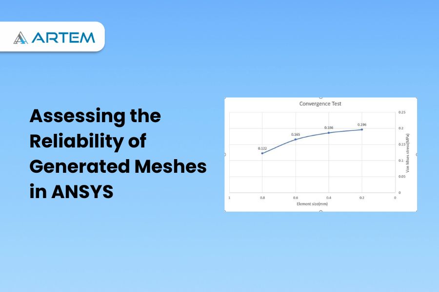
How can we understand that the mesh generated in ANSYS is reliable or not? The evaluation of a mesh generated in ANSYS or any other finite element analysis (FEA) software is a crucial step in ensuring the accuracy and significance of the results. Here are some factors to consider when assessing the reliability of a mesh: Mesh Quality Metrics: When assessing the reliability of a mesh in ANSYS or any other FEA software, various mesh quality metrics can be used to evaluate the quality of the elements. Here are some common mesh quality metrics that can be considered: 1.Aspect Ratio: Aspect ratio measures the elongation or distortion of an element. It is calculated by dividing the longest edge of an element by the shortest edge. A high aspect ratio indicates elongated or stretched elements, which can lead to inaccurate results. 2.Skewness: Skewness quantifies the deviation of an element from an ideal shape, typically an equilateral triangle (in 2D) or a regular tetrahedron (in 3D). High skewness values indicate distorted or skewed elements, which can adversely affect the accuracy of the solution. 3.Jacobian: Jacobian is a measure of the element’s deformation from its original shape. It calculates the volume change in an element during the deformation process. A low Jacobian value indicates significant deformation, which can lead to inaccurate results. 4.Orthogonality: Orthogonality measures the angle between adjacent edges or faces of an element. Higher orthogonality implies more orthogonal or perpendicular elements, which are desirable for accurate simulations. 5.Node Warping: Node warping measures the distortion of the nodes within an element. Excessive node warping can lead to inaccurate results and should be minimized. These mesh quality metrics are generally available within ANSYS or can be calculated using post-processing tools. It’s important to consider these metrics collectively and aim for a mesh that exhibits good quality across multiple criteria. However, it’s worth noting that the importance of each metric may vary depending on the specific simulation and problem at hand. Convergence Studies: Convergence studies in reliability analysis using ANSYS are essential to ensure accurate and reliable results. A convergence study involves systematically varying certain parameters, such as mesh size or number of iterations, and examining the corresponding changes in the results to determine the point at which further refinement does not significantly impact the outcome. The primary objective is to establish a level of confidence in the obtained results, ensuring that they are not unduly influenced by numerical errors or modeling assumptions. To conduct a convergence study, the analyst typically starts by defining an appropriate finite element model and specifying the necessary input parameters, such as material properties, loading conditions, and probabilistic distributions. Subsequently, the analysis is performed with a coarse mesh and a moderate number of iterations. The analyst then proceeds to systematically refine the mesh by increasing the number of elements or nodes and re-running the analysis. The obtained results are compared with those from the previous iteration, and the convergence behavior is evaluated. The process is repeated until a convergence criterion is met, indicating that further mesh refinement does not significantly alter the reliability metrics. Additionally, other factors, such as convergence with respect to the number of iterations or the level of discretization, may also be examined. The convergence study provides valuable insights into the sensitivity of the results to these parameters and aids in determining the appropriate level of refinement required for accurate reliability assessment. In conclusion, convergence studies play a crucial role in ensuring the reliability and accuracy of the obtained results. By systematically varying parameters and observing the convergence behavior, analysts can establish the appropriate level of mesh refinement or other numerical considerations required for robust reliability assessments. Solution Verification: Solution verification is an important step, aimed at validating the accuracy of the numerical solution and ensuring that it aligns with the expected behavior of the system under study. It involves comparing the results obtained from the ANSYS analysis with known analytical solutions or experimental data, if available. To perform solution verification in ANSYS for reliability analysis, the analyst starts by selecting benchmark problems or cases for which analytical solutions exist. These benchmarks should possess similar characteristics and features as the system being analyzed. The analyst then sets up the ANSYS model and applies the same input parameters used in the analytical solutions. Once the ANSYS analysis is complete, the results are compared to the known analytical solutions. Discrepancies between the two sets of results are carefully examined and analyzed. If the differences are within acceptable limits, it indicates that the ANSYS model and analysis are accurate and can be relied upon for reliability assessment. In cases where analytical solutions are not available, the analyst may resort to experimental data. In such scenarios, the ANSYS results are compared to the experimental measurements, and the level of agreement is evaluated. Any significant deviations or discrepancies between the ANSYS predictions and the experimental data need to be investigated and addressed. Solution verification in ANSYS serves as a critical quality assurance step. It helps validate the accuracy and reliability of the numerical solution by comparing it with established benchmarks or experimental data. This process instills confidence in the ANSYS analysis and ensures that the obtained results can be trusted for making informed decisions regarding the reliability of the system under consideration. Mesh Sensitivity Analysis: Performing a sensitivity analysis on the mesh can help determine the impact of mesh density on the results. By systematically refining or coarsening the mesh and observing the changes in the results, you can gain insights into the mesh’s reliability. The objective is to determine the appropriate level of mesh refinement necessary to obtain accurate and reliable results. To start with, the analyst starts by creating an initial finite element model with a certain mesh density. The model includes all the necessary input parameters, such as material properties, loading conditions, and probabilistic distributions. The analysis is then performed to obtain the reliability metrics, such as failure probabilities or safety factors. Next, the analyst systematically varies
In the world of engineering and product design, simulation is a game-changer. It allows engineers and designers to virtually test and validate their ideas, saving time, reducing costs, and improving product performance. Ansys Workbench is at the forefront of simulation technology, and this article is your guide to mastering its capabilities and harnessing its power for comprehensive simulations. The Significance of Ansys Workbench Ansys Workbench is a versatile and powerful simulation platform used by engineers across the globe to solve complex engineering challenges. It offers a wide array of simulation tools, including structural analysis, fluid dynamics, electromagnetic simulation, and more. Here’s why Ansys Workbench is so significant: 1. Simulation Accuracy: Ansys Workbench provides highly accurate results, ensuring that the virtual tests closely mimic real-world behavior. 2. Multidisciplinary Simulation: It allows engineers to perform simulations in multiple disciplines, enabling a holistic approach to product development. 3. Optimization: With Ansys Workbench, you can optimize your designs for performance, cost, and other critical factors. 4. Time and Cost Savings: By identifying and solving problems in the virtual environment, Ansys Workbench reduces the need for costly physical prototypes and extensive testing. The Journey to Mastery Mastering Ansys Workbench is a journey, and it involves several key steps: 1. Understanding the Interface: Familiarize yourself with the Ansys Workbench interface, and learn how to navigate through its various modules and tools. 2. Defining the Problem: To perform an effective simulation, you need to clearly define the problem and the parameters you want to study. 3. Building the Model: Learn how to create the 3D model of your design within Ansys Workbench. This involves geometry creation and meshing. 4. Setting Up Boundary Conditions: Define the environment and constraints under which your design will be tested. This is a critical aspect of simulation setup. 5. Running Simulations: Ansys Workbench provides different solvers for various types of simulations. Understand how to set up and run simulations efficiently. 6. Analyzing Results: After running simulations, it’s crucial to analyze and interpret the results. This is where the real insights are gained. 7. Iteration and Optimization: Based on the results, make necessary design changes and iterate the simulation to optimize your product’s performance. Mastery of Ansys Workbench opens doors to various benefits: – Improved Product Quality: By thoroughly testing your designs, you can catch and correct issues before production, ensuring higher-quality products. – Cost Reduction: Reduced reliance on physical prototypes and testing can lead to significant cost savings. – Faster Time to Market: Quick and accurate simulations help you bring your products to market faster, gaining a competitive edge. – Innovation: Ansys Workbench allows you to push the boundaries of what’s possible, fostering innovation and groundbreaking designs. Start Your Journey Today Becoming a master of Ansys Workbench is a commitment to constant learning and improvement. It’s a path to becoming a more effective, knowledgeable, and innovative engineer or designer. Whether you’re a student, a professional engineer, or a product designer, the comprehensive guide to mastering Ansys Workbench is your key to unlocking the potential of simulation technology and achieving excellence in your field. So, don’t wait—start your journey to mastering Ansys Workbench today. Elevate your engineering skills with Artem Academy. Learn the intricacies of this powerful finite element pre-processor software used in various industries. Master meshing and modeling for real-world applications. Enroll now and enhance your engineering career with us.
- 1
- 2