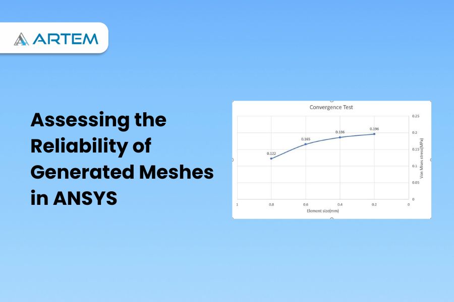
How can we understand that the mesh generated in ANSYS is reliable or not? The evaluation of a mesh generated in ANSYS or any other finite element analysis (FEA) software is a crucial step in ensuring the accuracy and significance of the results. Here are some factors to consider when assessing the reliability of a mesh: Mesh Quality Metrics: When assessing the reliability of a mesh in ANSYS or any other FEA software, various mesh quality metrics can be used to evaluate the quality of the elements. Here are some common mesh quality metrics that can be considered: 1.Aspect Ratio: Aspect ratio measures the elongation or distortion of an element. It is calculated by dividing the longest edge of an element by the shortest edge. A high aspect ratio indicates elongated or stretched elements, which can lead to inaccurate results. 2.Skewness: Skewness quantifies the deviation of an element from an ideal shape, typically an equilateral triangle (in 2D) or a regular tetrahedron (in 3D). High skewness values indicate distorted or skewed elements, which can adversely affect the accuracy of the solution. 3.Jacobian: Jacobian is a measure of the element’s deformation from its original shape. It calculates the volume change in an element during the deformation process. A low Jacobian value indicates significant deformation, which can lead to inaccurate results. 4.Orthogonality: Orthogonality measures the angle between adjacent edges or faces of an element. Higher orthogonality implies more orthogonal or perpendicular elements, which are desirable for accurate simulations. 5.Node Warping: Node warping measures the distortion of the nodes within an element. Excessive node warping can lead to inaccurate results and should be minimized. These mesh quality metrics are generally available within ANSYS or can be calculated using post-processing tools. It’s important to consider these metrics collectively and aim for a mesh that exhibits good quality across multiple criteria. However, it’s worth noting that the importance of each metric may vary depending on the specific simulation and problem at hand. Convergence Studies: Convergence studies in reliability analysis using ANSYS are essential to ensure accurate and reliable results. A convergence study involves systematically varying certain parameters, such as mesh size or number of iterations, and examining the corresponding changes in the results to determine the point at which further refinement does not significantly impact the outcome. The primary objective is to establish a level of confidence in the obtained results, ensuring that they are not unduly influenced by numerical errors or modeling assumptions. To conduct a convergence study, the analyst typically starts by defining an appropriate finite element model and specifying the necessary input parameters, such as material properties, loading conditions, and probabilistic distributions. Subsequently, the analysis is performed with a coarse mesh and a moderate number of iterations. The analyst then proceeds to systematically refine the mesh by increasing the number of elements or nodes and re-running the analysis. The obtained results are compared with those from the previous iteration, and the convergence behavior is evaluated. The process is repeated until a convergence criterion is met, indicating that further mesh refinement does not significantly alter the reliability metrics. Additionally, other factors, such as convergence with respect to the number of iterations or the level of discretization, may also be examined. The convergence study provides valuable insights into the sensitivity of the results to these parameters and aids in determining the appropriate level of refinement required for accurate reliability assessment. In conclusion, convergence studies play a crucial role in ensuring the reliability and accuracy of the obtained results. By systematically varying parameters and observing the convergence behavior, analysts can establish the appropriate level of mesh refinement or other numerical considerations required for robust reliability assessments. Solution Verification: Solution verification is an important step, aimed at validating the accuracy of the numerical solution and ensuring that it aligns with the expected behavior of the system under study. It involves comparing the results obtained from the ANSYS analysis with known analytical solutions or experimental data, if available. To perform solution verification in ANSYS for reliability analysis, the analyst starts by selecting benchmark problems or cases for which analytical solutions exist. These benchmarks should possess similar characteristics and features as the system being analyzed. The analyst then sets up the ANSYS model and applies the same input parameters used in the analytical solutions. Once the ANSYS analysis is complete, the results are compared to the known analytical solutions. Discrepancies between the two sets of results are carefully examined and analyzed. If the differences are within acceptable limits, it indicates that the ANSYS model and analysis are accurate and can be relied upon for reliability assessment. In cases where analytical solutions are not available, the analyst may resort to experimental data. In such scenarios, the ANSYS results are compared to the experimental measurements, and the level of agreement is evaluated. Any significant deviations or discrepancies between the ANSYS predictions and the experimental data need to be investigated and addressed. Solution verification in ANSYS serves as a critical quality assurance step. It helps validate the accuracy and reliability of the numerical solution by comparing it with established benchmarks or experimental data. This process instills confidence in the ANSYS analysis and ensures that the obtained results can be trusted for making informed decisions regarding the reliability of the system under consideration. Mesh Sensitivity Analysis: Performing a sensitivity analysis on the mesh can help determine the impact of mesh density on the results. By systematically refining or coarsening the mesh and observing the changes in the results, you can gain insights into the mesh’s reliability. The objective is to determine the appropriate level of mesh refinement necessary to obtain accurate and reliable results. To start with, the analyst starts by creating an initial finite element model with a certain mesh density. The model includes all the necessary input parameters, such as material properties, loading conditions, and probabilistic distributions. The analysis is then performed to obtain the reliability metrics, such as failure probabilities or safety factors. Next, the analyst systematically varies

A finite element method (FEM) is a numerical method used for solving engineering and mathematical problems involving the distribution of complex systems or structures into smaller, simpler, and interconnected subdomains. A set of mathematical equations approximates the behavior of each element. It has been widely applied in many fields, including structural analysis, heat transfer, fluid dynamics, and electromagnetics. The history of the Finite Element Method dates back to the early 1940s, with the work of Richard Courant, a German mathematician. Courant, along with his collaborators, developed a numerical technique called the Ritz-Galerkin method for approximating solutions to differential equations. This method laid the foundation for what would later become the Finite Element Method. In the late 1950s, engineers and mathematicians began developing the concept of dividing structures into small subdomains to simplify analysis. Notable pioneers in the development of FEM during this time include J.H. Argyris, Ray W. Clough, and Olek Zienkiewicz. They published seminal papers outlining the mathematical foundations and practical applications of the method. The first recorded use of the term “finite element” in the context of structural analysis dates back to the 1960s. It was coined by two engineers, Ray W. Clough and G. Temple, in their 1965 paper titled “The Finite Element Method in Plane Stress Analysis.” In this paper, Clough and Temple described their approach to solving plane stress analysis problems using a numerical method they referred to as the “finite element method.” They introduced the concept of dividing the domain into small subdomains (finite elements) and deriving the governing equations for each element. The authors highlighted the benefits of this method, including its ability to handle irregular geometries and complex boundary conditions. Since then, the term “finite element” has become the widely accepted terminology for this numerical technique, and it has been used consistently in subsequent research papers, books, and software development related to the method. The first book on the finite element method was “The Mathematical Foundations of the Finite Element Method” by Jacques Louis Lions and Olgierd C. Zienkiewicz. It was published in 1972. This book provided a comprehensive mathematical treatment of the finite element method, outlining the underlying principles and mathematical formulations involved in solving problems using the method. It became a seminal reference for researchers and practitioners in the field and played a significant role in the popularization and advancement of the finite element method. In 1960, Zienkiewicz, a British engineer, published a landmark paper titled “The Finite Element Method in Structural and Continuum Mechanics,” which introduced the term “finite element method” and presented the formulation of the method for structural analysis. Zienkiewicz’s work helped popularize the method and laid the groundwork for its subsequent development and application in various fields. The first finite element software was developed by a team led by Richard H. Gallagher at the Structural Analysis Group at the University of California, Berkeley. The software, known as STRESS, was created in the early 1960s and was primarily used for structural analysis. STRESS was one of the earliest implementations of the finite element method and was initially developed for linear elasticity problems. It allowed engineers to input the geometry, material properties, and boundary conditions of a structure and then perform stress analysis calculations using the finite element method. The software utilized the matrix displacement method, which is a precursor to the more widely used displacement-based formulation. While STRESS was significant in pioneering the application of the finite element method, it was a relatively simple program compared to modern finite element software packages. Over the years, the development of commercial software such as NASTRAN, ABAQUS, ANSYS, and many others has greatly expanded the capabilities and applications of the finite element method. Expansion and Diversification: Throughout the 1970s and 1980s, the finite element method expanded rapidly into various fields of engineering and science. Researchers extended its applications to areas such as heat transfer, fluid dynamics, and electromagnetics. The method’s flexibility and ability to handle complex geometries and boundary conditions contributed to its popularity. Advancements and Refinements: Over the years, researchers have continually refined and enhanced the finite element method. The development of powerful computers in the latter half of the 20th century greatly accelerated the progress of the Finite Element Method. The availability of computational resources enabled engineers and scientists to solve more complex problems and perform more accurate simulations. Commercial software packages dedicated to finite element analysis (FEA) emerged, making the method more accessible and practical for engineering applications. Since its inception, the Finite Element Method has continued to evolve, with improvements in element formulations, numerical algorithms, and computer hardware. It has become a standard tool in engineering and scientific communities, offering efficient and accurate solutions for a wide range of problems involving structural, thermal, fluid, and electromagnetic analyses. Today, the Finite Element Method remains a prominent and indispensable numerical technique, widely used in industries such as aerospace, automotive, civil engineering, and biomechanics, among others. Its versatility and robustness have made it a cornerstone of modern computational engineering and analysis.

In the world of engineering and product design, simulation is a game-changer. It allows engineers and designers to virtually test and validate their ideas, saving time, reducing costs, and improving product performance. Ansys Workbench is at the forefront of simulation technology, and this article is your guide to mastering its capabilities and harnessing its power for comprehensive simulations. The Significance of Ansys Workbench Ansys Workbench is a versatile and powerful simulation platform used by engineers across the globe to solve complex engineering challenges. It offers a wide array of simulation tools, including structural analysis, fluid dynamics, electromagnetic simulation, and more. Here’s why Ansys Workbench is so significant: 1. Simulation Accuracy: Ansys Workbench provides highly accurate results, ensuring that the virtual tests closely mimic real-world behavior. 2. Multidisciplinary Simulation: It allows engineers to perform simulations in multiple disciplines, enabling a holistic approach to product development. 3. Optimization: With Ansys Workbench, you can optimize your designs for performance, cost, and other critical factors. 4. Time and Cost Savings: By identifying and solving problems in the virtual environment, Ansys Workbench reduces the need for costly physical prototypes and extensive testing. The Journey to Mastery Mastering Ansys Workbench is a journey, and it involves several key steps: 1. Understanding the Interface: Familiarize yourself with the Ansys Workbench interface, and learn how to navigate through its various modules and tools. 2. Defining the Problem: To perform an effective simulation, you need to clearly define the problem and the parameters you want to study. 3. Building the Model: Learn how to create the 3D model of your design within Ansys Workbench. This involves geometry creation and meshing. 4. Setting Up Boundary Conditions: Define the environment and constraints under which your design will be tested. This is a critical aspect of simulation setup. 5. Running Simulations: Ansys Workbench provides different solvers for various types of simulations. Understand how to set up and run simulations efficiently. 6. Analyzing Results: After running simulations, it’s crucial to analyze and interpret the results. This is where the real insights are gained. 7. Iteration and Optimization: Based on the results, make necessary design changes and iterate the simulation to optimize your product’s performance. Mastery of Ansys Workbench opens doors to various benefits: – Improved Product Quality: By thoroughly testing your designs, you can catch and correct issues before production, ensuring higher-quality products. – Cost Reduction: Reduced reliance on physical prototypes and testing can lead to significant cost savings. – Faster Time to Market: Quick and accurate simulations help you bring your products to market faster, gaining a competitive edge. – Innovation: Ansys Workbench allows you to push the boundaries of what’s possible, fostering innovation and groundbreaking designs. Start Your Journey Today Becoming a master of Ansys Workbench is a commitment to constant learning and improvement. It’s a path to becoming a more effective, knowledgeable, and innovative engineer or designer. Whether you’re a student, a professional engineer, or a product designer, the comprehensive guide to mastering Ansys Workbench is your key to unlocking the potential of simulation technology and achieving excellence in your field. So, don’t wait—start your journey to mastering Ansys Workbench today. Elevate your engineering skills with Artem Academy. Learn the intricacies of this powerful finite element pre-processor software used in various industries. Master meshing and modeling for real-world applications. Enroll now and enhance your engineering career with us.

In any analysis and simulation tool for structural analysis, various types of loads can be defined to analyze the behavior of structures. It’s crucial to understand that the specific types of loads available can vary. Any CAE tool, offers a wide range of load options to accurately simulate real-world operating conditions and effectively evaluate structural responses. These loads are applied externally on the node or element based on the type of load acting. The units of load system should be in line with the geometric parameters to maintain consistency. Here are some common types of loads used in analysis and simulations: Point Load: A concentrated load is applied at a specific point or location on the structure. It is typically represented by its magnitude, direction, and application point. The magnitude of the point load represents the intensity or strength of the force, and it can be specified in units of force (such as Newtons or pounds) or as a pressure (such as Pascal or psi). The direction of the point load indicates the orientation or alignment of the force vector. It can be defined in terms of its components along the X, Y, and Z axes or by specifying angles concerning the coordinate system of the model. The application point of the point load is the specific node or element where the load is applied. It is important to accurately locate the application point since it influences the response of the structure and the stress distribution within the finite element model. By applying point loads at appropriate locations within the finite element model, engineers can simulate and analyze the effects of localized forces, such as concentrated loads, point forces, or reactions, on the behavior and performance of structures. Distributed Load: A load that is spread over an area or along a line. It is defined by its intensity or pressure and its distribution pattern. A uniform load is characterized by its magnitude and direction. The magnitude of the uniform load represents the intensity or strength of the load per unit length, area, or volume. It can be specified in units of force per unit length (such as Newtons per meter or pounds per foot), force per unit area (such as Newtons per square meter or pounds per square foot), or force per unit volume (such as Newtons per cubic meter or pounds per cubic foot). The direction of the uniform load indicates the orientation or alignment of the load vector. It can be defined as a constant force or pressure acting in a specific direction, or it can be represented by a vector with components along the X, Y, and Z axes. By applying uniform loads over certain regions or surfaces within the finite element model, engineers can simulate and analyze the effects of distributed forces, such as self-weight, wind loads, pressure loads, or gravitational loads, on the structural response and behavior. The FEM calculations take into account the distribution of the load and its influence on the deformation, stress, and strain throughout the model.’ Pressure Load: A uniform or non-uniform pressure acting on the surface of a structure. It can represent forces such as fluid or gas pressure. pressure load is characterized by its magnitude and direction. The magnitude of the pressure load represents the intensity or strength of the pressure exerted per unit area. It is typically specified in units of force per unit area, such as Pascal (Pa) or pounds per square inch (psi). The direction of the pressure load indicates the orientation or alignment of the load vector. It is defined as a normal force acting perpendicular to the surface on which the pressure is applied. The pressure load can be distributed uniformly over the surface, or it can vary spatially based on the specific requirements of the problem. By applying pressure loads to surfaces within the finite element model, engineers can simulate and analyze the effects of external forces, such as fluid or gas pressure, on the structural response and behavior. The FEM calculations take into account the distribution of the pressure load and its influence on the deformation, stress, and strain throughout the model. This enables engineers to evaluate the structural integrity, performance, and safety of the system under the applied pressure conditions. Thermal Load: A load resulting from temperature variations. It can include uniform or non-uniform temperature distributions or temperature differences between different parts of the structure. In other words, it represents the influence of thermal conditions and thermal gradients on the behavior and response of the finite element model. Thermal loads are characterized by the temperature distribution and the corresponding thermal expansion or contraction of the material. When a structure is subjected to temperature changes, it experiences thermal strains and stresses due to the differential expansion or contraction of its components. Temperature values can be prescribed at specific points, edges, or surfaces of the model to represent the known or desired temperature distribution. These boundary conditions may be constant or vary over time. Temperature differences across the model can be specified to represent thermal gradients. This can be achieved by assigning different temperature values to different parts of the model or by defining temperature differences between specific points. By considering thermal loads in FEM, engineers can analyze the structural response to temperature changes and evaluate the thermal stress, deformation, and potential failures that may occur due to thermal effects. This enables them to design structures that can withstand the thermal conditions they are subjected to, ensuring safety and optimal performance. Displacement Load: A load that represents the prescribed displacement or deformation of a particular point or region in the structure. It is used to simulate constraints or external movements. It represents a prescribed displacement boundary condition that simulates the effect of external constraints or movements on the structure. A displacement load is characterized by the magnitude and direction of the prescribed displacements. Instead of applying forces or pressures, the displacement load directly imposes specific deformations or movements on the model. Specifying

Supports are arguably one of the most important aspects of a structure, as it specifies how the forces within the structure are transferred to the ground.

Supports are arguably one of the most important aspects of a structure, as it specifies how the forces within the structure are transferred to the ground.
Supports are arguably one of the most important aspects of a structure, as it specifies how the forces within the structure are transferred to the ground.

Supports are arguably one of the most important aspects of a structure, as it specifies how the forces within the structure are transferred to the ground.

Supports are arguably one of the most important aspects of a structure, as it specifies how the forces within the structure are transferred to the ground.

Supports are arguably one of the most important aspects of a structure, as it specifies how the forces within the structure are transferred to the ground.