Taking about the dynamics of the fluid first let us talk about the forces that are acted on the fluid in general. Following are the forces that act but vary from case to case and are also dependent on the assumptions we consider during any derivation as well as our understanding.
- Gravity Force (
 )
) - Pressure Force (
 )
) - Viscous Force (
 )
) - Force due to compressibility (
 )
) - Force due to turbulence (
 )
) - Surface Tension Force (
 )
)
In this case, when we consider this force then we can call it Newton’s equation of Motion.

In the case when all the forces except the surface tension force and compressibility forces are acted the resultant equation is termed as Reynold’s Equation.

Now if we talk about the case where, only gravity force, pressure force, and viscous are considered then the equation is termed as Navier Strokes Equation.

Now coming back to the discussion of Euler, the forces considered during its derivations are gravity force and Pressure Force. For more details derivation of the above equations can be looked upon.
One of the most important things that need to be coupled with Bernoulli’s equation is the Continuity Equation. This conveys the message of mass conservation. In simple words, we can say that it balances the mass and keeps a check on it so that our work never fails. It means the amount of mass entering into a section and the amount of mass exiting a section should be balanced. Continuity equation helps a lot while problem-solving using Bernoulli’s equation.
ρAV = C
Where ρ = Density of the fluid
A = Area of the Cross- section
V = Velocity of the Fluid
After a brief overview of the different kinds of forces that are considered during different equations, lets look in the assumptions of Bernoulli’s Equation. We will, for now, keep our discussion limited to Incompressible Fluids otherwise the level of the complexities will increase
The assumptions are :
- Flow is always considered on a streamline
- The Fluid is assumed to be steady
- Effect of irreversibilities, viscous forces, and friction are not considered here
- The fluid is always treated as incompressible ( density = constant )
The derivation of Bernoulli’s equation revolves around the linear momentum principle.
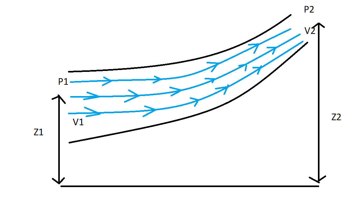
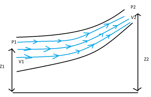
Bernoulli’s equation is basically the combination of pressure, velocity and elevation. Each term of the equation is generally referred to as head namely, Pressure head, Kinetic Energy and Elevation head. These three terms are added and hence net conservation of energy takes place. This equation finds its application in many fields including Aerodynamics.
P + ρgh + (½)ρv2 = C
Where P = Static Pressure
ρgh = Potential Energy
(½)ρv2 = Kinetic Energy
Lets now look into each term of Bernoulli’s equation individually
Pressure Head: Pressure Energy per unit weight, P here means the static pressure. Energy changes and the head changes because of the actual pressure.
Velocity Head: Kinetic Energy per unit mass, The changes in the head take place because of the flow of the fluid.
Elevation Head: Potential Energy per unit mass, the change in the head takes place because of the elevation of the 2 points which are taken into consideration.
Every equation comes with a set of warning labels in the form of assumptions, as it puts a limit on its application and usage. These also help us to not land on wrong results. However there are very idealistic assumptions taken in the derivation of Bernoulli’s equation, we tend to find situations where we can easily apply these results.
As the frictions remain unavoidable in most cases, Bernoulli’s equation is also adjusted a little to help us in those situations.
Let us now see some of the examples where we should not apply this equation.
Case 1: We should never apply them in the very long narrow flow passage, the reason is because of the more length and less effective diameter the friction becomes really significant.
Case 2: Near the boundary layer, also the friction becomes very high and the generation of shear stress and rotational fluid happens
Case 3: In the case of diverging sections care has to be taken as in the diverging section the chances of flow separation are very high which can give rise to wake formation. The generated wake gives rise to irreversibility and high viscosity.
Case 4: Whenever Mach number is greater than 0.3, below 0.3 the fluid is assumed to be incompressible. Above 0.3, this assumption starts to fail as fluid tends to move towards compressibility (i.e. there is a significant change in the density)
Case 5: The sections where temperature changes are significant. The temperature change causes an effect on the density, which makes fluid compressible.