
In any analysis and simulation tool for structural analysis, various types of loads can be defined to analyze the behavior of structures. It’s crucial to understand that the specific types of loads available can vary. Any CAE tool, offers a wide range of load options to accurately simulate real-world operating conditions and effectively evaluate structural responses. These loads are applied externally on the node or element based on the type of load acting. The units of load system should be in line with the geometric parameters to maintain consistency.
Here are some common types of loads used in analysis and simulations:
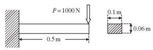
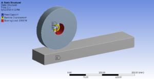
Point Load:
A concentrated load is applied at a specific point or location on the structure. It is typically represented by its magnitude, direction, and application point.
The magnitude of the point load represents the intensity or strength of the force, and it can be specified in units of force (such as Newtons or pounds) or as a pressure (such as Pascal or psi). The direction of the point load indicates the orientation or alignment of the force vector. It can be defined in terms of its components along the X, Y, and Z axes or by specifying angles concerning the coordinate system of the model.
The application point of the point load is the specific node or element where the load is applied. It is important to accurately locate the application point since it influences the response of the structure and the stress distribution within the finite element model.
By applying point loads at appropriate locations within the finite element model, engineers can simulate and analyze the effects of localized forces, such as concentrated loads, point forces, or reactions, on the behavior and performance of structures.
Distributed Load:
A load that is spread over an area or along a line. It is defined by its intensity or pressure and its distribution pattern. A uniform load is characterized by its magnitude and direction. The magnitude of the uniform load represents the intensity or strength of the load per unit length, area, or volume. It can be specified in units of force per unit length (such as Newtons per meter or pounds per foot), force per unit area (such as Newtons per square meter or pounds per square foot), or force per unit volume (such as Newtons per cubic meter or pounds per cubic foot).
The direction of the uniform load indicates the orientation or alignment of the load vector. It can be defined as a constant force or pressure acting in a specific direction, or it can be represented by a vector with components along the X, Y, and Z axes.
By applying uniform loads over certain regions or surfaces within the finite element model, engineers can simulate and analyze the effects of distributed forces, such as self-weight, wind loads, pressure loads, or gravitational loads, on the structural response and behavior. The FEM calculations take into account the distribution of the load and its influence on the deformation, stress, and strain throughout the model.’
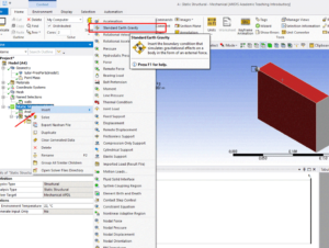
Pressure Load:
A uniform or non-uniform pressure acting on the surface of a structure. It can represent forces such as fluid or gas pressure. pressure load is characterized by its magnitude and direction. The magnitude of the pressure load represents the intensity or strength of the pressure exerted per unit area. It is typically specified in units of force per unit area, such as Pascal (Pa) or pounds per square inch (psi).
The direction of the pressure load indicates the orientation or alignment of the load vector. It is defined as a normal force acting perpendicular to the surface on which the pressure is applied. The pressure load can be distributed uniformly over the surface, or it can vary spatially based on the specific requirements of the problem.
By applying pressure loads to surfaces within the finite element model, engineers can simulate and analyze the effects of external forces, such as fluid or gas pressure, on the structural response and behavior. The FEM calculations take into account the distribution of the pressure load and its influence on the deformation, stress, and strain throughout the model. This enables engineers to evaluate the structural integrity, performance, and safety of the system under the applied pressure conditions.
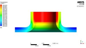
Thermal Load:
A load resulting from temperature variations. It can include uniform or non-uniform temperature distributions or temperature differences between different parts of the structure. In other words, it represents the influence of thermal conditions and thermal gradients on the behavior and response of the finite element model.
Thermal loads are characterized by the temperature distribution and the corresponding thermal expansion or contraction of the material. When a structure is subjected to temperature changes, it experiences thermal strains and stresses due to the differential expansion or contraction of its components.
Temperature values can be prescribed at specific points, edges, or surfaces of the model to represent the known or desired temperature distribution. These boundary conditions may be constant or vary over time.
Temperature differences across the model can be specified to represent thermal gradients. This can be achieved by assigning different temperature values to different parts of the model or by defining temperature differences between specific points.
By considering thermal loads in FEM, engineers can analyze the structural response to temperature changes and evaluate the thermal stress, deformation, and potential failures that may occur due to thermal effects. This enables them to design structures that can withstand the thermal conditions they are subjected to, ensuring safety and optimal performance.
Displacement Load:
A load that represents the prescribed displacement or deformation of a particular point or region in the structure. It is used to simulate constraints or external movements. It represents a prescribed displacement boundary condition that simulates the effect of external constraints or movements on the structure.
A displacement load is characterized by the magnitude and direction of the prescribed displacements. Instead of applying forces or pressures, the displacement load directly imposes specific deformations or movements on the model.
Specifying specific displacements at selected points to simulate known movements or constraints. These displacements can be in one or more directions and can vary over time.
With this load engineers can analyze the structural response to prescribed displacements and evaluate the resulting stresses, strains, and deformation patterns. This helps in understanding the behavior of the structure under various displacement conditions and designing structures that can withstand the anticipated displacements or constraints.
Gravity Load:
The load due to the weight of the structure or its components. It is automatically applied in the vertical direction based on the material properties and geometry. It refers to the effect of gravitational forces acting on a structure or system. It represents the weight or mass of the structure and any additional loads due to gravity, such as self-weight or externally applied gravitational loads.
Gravity loads are typically applied to simulate the influence of the Earth’s gravitational field on the structural response. They are characterized by their magnitude and direction.
The magnitude of a gravity load is determined by the weight or mass of the components in the model. It is often specified as a force, such as Newtons or pounds, or as a distributed load, such as force per unit length, area, or volume, depending on the type of element being analyzed.
The direction of a gravity load is typically vertical, acting in the opposite direction of the gravitational field. However, in certain cases, gravity loads may also have horizontal components or be applied at inclined angles, depending on the specific problem being considered. The distribution of gravity loads accounts for the material density and considers the specific geometry and layout of the model.
Inertia Load:
The load due to the acceleration or deceleration of the structure. It considers the mass and motion of the structure and is commonly used in dynamic analyses and refers to the effect of inertial forces acting on a structure or system due to its acceleration or deceleration. It represents the response of the structure to changes in its motion or velocity.
Inertia loads are characterized by their magnitude and direction, which depend on the mass distribution and motion of the structure. They are typically associated with dynamic analyses or transient phenomena, where the structural response to acceleration or deceleration is of interest.
The magnitude of an inertia load is determined by the mass of the structure and the rate of change of its velocity. It is often specified as a force or distributed load, depending on the specific problem being analyzed.
The direction of an inertia load is typically aligned with the acceleration or deceleration vector. It depends on the motion of the structure and can be in any direction, including combinations of horizontal, vertical, or angular motions. The mass distribution of the structure is considered along with the acceleration or deceleration profile. The loads are distributed to the finite elements based on their respective masses and locations within the model.
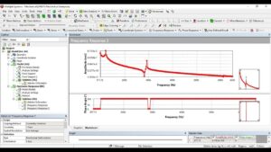
Harmonic Load:
A periodic load that varies sinusoidally over time. It is often used to simulate vibration or cyclic loading conditions and refers to a time-varying load that follows a sinusoidal or harmonic pattern. It represents a periodic load or excitation applied to a structure or system.
Harmonic loads are characterized by their frequency, amplitude, and phase. They are typically associated with dynamic analyses and the study of structures subjected to cyclic or oscillatory forces.
The frequency of a harmonic load represents the rate at which the load oscillates or repeats itself within a given time period. It is usually specified in Hertz (Hz) or radians per second (rad/s). The frequency determines the number of cycles or oscillations the load completes in a given time interval.
The amplitude of a harmonic load represents the peak or maximum value of the load during each cycle. It represents the intensity or strength of the load and is typically specified in units of force or pressure.
The phase of a harmonic load refers to the shift or displacement in time of the load relative to a reference point. It determines the starting point or position of the load waveform within a cycle and is usually specified in degrees or radians. The load is defined as a function of time or as a sinusoidal expression. The load is then applied to the appropriate nodes or elements within the finite element model based on the specified frequency, amplitude, and phase.
This harmonic load allows for the assessment of fatigue life, resonant frequencies, dynamic amplifications, and other dynamic effects that may influence the structural integrity and performance of the system.
Impact Load:
An impact load refers to a sudden and transient load applied to a structure or system due to a rapid change in velocity or the collision of an object with the structure. It represents the effect of an impulsive force on the structural response.
Impact loads are characterized by their magnitude, duration, and application location. They typically involve high-intensity forces that act over a short duration, resulting in a rapid change in momentum or energy transfer.
The magnitude of an impact load represents the intensity or strength of the force exerted on the structure. It is typically specified in units of force or pressure.
The duration of an impact load refers to the time interval over which the load acts on the structure. It is relatively short compared to the time scale of the structural response and is often specified as an instantaneous load.
The application location of an impact load indicates the specific point or region where the load is applied to the structure. It is important to accurately locate the application point to simulate the localized effect of the impact. The transient analysis technique is used to capture the dynamic response of the structure to the impulsive force.
With this load one can analyze the structural response to sudden and transient events, such as collisions, explosions, or drop impacts. This allows for the evaluation of the structural integrity, stress levels, deformation, and potential failure modes resulting from impulsive loading conditions.
These are some examples of loads that can be applied in CAE tools to simulate different operating conditions and evaluate the structural response. The specific types of loads available may vary depending on the CAE software being used.
To gain a comprehensive understanding of these load types and how to apply them in varies CAE tool, you may consider exploring resources like Artem Academy. Such educational platforms can provide in-depth training and guidance on utilizing ANSYS’s load capabilities for successful structural analysis.