
If you’re aspiring to carve your niche in the dynamic world of automotive alignment engineering, mastering Computer-Aided Design (CAD) is a crucial pit stop on your career journey. The question then arises: which CAD software is the best companion for engineers in this field? Buckle up as we navigate through the options and unveil the ideal CAD destination for your automotive alignment career. The CAD Landscape: Navigating the Options The realm of CAD is vast, with various tools catering to different industries and design needs. When it comes to automotive alignment, two major players stand out: Siemens NX and CATIA 1. Siemens NX: Driving Precision and Integration Why Siemens NX? Parametric Modeling Skill: Siemens NX is renowned for its robust parametric modeling capabilities. For automotive alignment engineers, this means the ability to create and modify 3D models with ease, ensuring precise alignment specifications are met. Integrated Simulation: In the automotive world, simulation is key. Siemens NX offers comprehensive simulation tools, allowing engineers to predict and optimize the performance of alignment systems before they hit the road. Collaboration and Integration: Siemens NX seamlessly integrates with other Siemens solutions, providing a unified platform for design, simulation, and manufacturing. This integration ensures a smooth workflow, vital for automotive alignment projects with multidisciplinary requirements. 2. CATIA: Streamlining Complex Designs Why CATIA? Surface Modeling Excellence: CATIA is renowned for its advanced surface modeling capabilities. This is a game-changer for automotive alignment engineers dealing with the sleek and aerodynamic designs of modern vehicles. Collaborative Design: CATIA fosters collaboration, allowing engineers to work concurrently on different aspects of a design. In the context of automotive alignment, where various components must work in harmony, this collaborative feature is invaluable. Industry Dominance: CATIA has a strong presence in the automotive industry, making it a preferred choice for many automotive manufacturers. Learning CATIA can open doors to opportunities in major automotive companies. Choosing Your CAD Vehicle: A Personal Journey The choice between Siemens NX and CATIA ultimately depends on your specific career goals, the industry landscape in your region, and your personal preferences. Here are a few factors to consider: Industry Demand: Research the companies in your region or the ones you aspire to work for. Some may have a preference for Siemens NX, while others might lean towards CATIA. Learning Curve: Both Siemens NX and CATIA have learning curves, but your personal learning style might align better with one over the other. Consider exploring trial versions or introductory courses to get a feel for each. Future Growth: Look into the future development plans of each CAD software. Consider which one aligns with the evolving trends and technologies in the automotive alignment field. Aspect Siemens NX CATIA Industry Adoption Widely used in automotive and aerospace industries. Prevalent in automotive, aerospace, and industrial design. Parametric Modeling Strong parametric modeling capabilities. Robust parametric modeling with advanced features. Surface Modeling Excellent surface modeling for complex designs. Known for advanced and precise surface modeling. Assembly Design Efficient assembly design tools with intelligent components. Powerful assembly design capabilities with collaboration features. Simulation and Analysis Integrated simulation tools for structural, thermal, and fluid analysis. Comprehensive simulation and analysis capabilities. Collaboration Capabilities Seamless integration with Teamcenter for PLM and collaborative design. Collaboration tools facilitate concurrent design among team members. Electrical Systems Design Provides capabilities for electrical systems design. Strong support for electrical systems design and integration. CAM (Computer-Aided Manufacturing) Integrated CAM solutions for manufacturing processes. Extensive CAM tools for a range of manufacturing applications. Industry Standards Compliance Compliant with industry standards like ISO 16792 (STEP AP242). Known for compliance with various industry standards. User Interface User-friendly interface, easier for beginners. Interface design may have a steeper learning curve. Customization and Extensions Extensive customization options and a wide range of extensions. Offers customization options but may have fewer extensions. Cost Consideration Licensing and maintenance costs can be relatively high. Cost structure may vary, and licensing costs can be significant. Conclusion: Steering Toward Success As you rev up your career in automotive alignment engineering, remember that both Siemens NX and CATIA are powerful tools with unique strengths. The best CAD for you is the one that aligns with your career goals, the industry landscape, and your personal preferences. So, buckle up, choose your CAD vehicle wisely, and enjoy the ride toward a successful and fulfilling career in automotive alignment engineering.

Congratulations, graduate! You’re on the tip of diving into the exciting world of Computer-Aided Design (CAD). As you embark on this journey, a critical decision awaits: which CAD tool should you learn to kickstart your career? In this blog, we’ll navigate through the industry landscapes of three prominent CAD tools — SolidWorks, Siemens NX, and CATIA — to help you make an informed choice tailored to your career aspirations. 1. SolidWorks: Bridging Simplicity and Power Industry Recognition: SolidWorks has carved a niche for itself in industries ranging from product design to consumer goods. Its user-friendly interface and ease of learning make it a popular choice, especially for small to mid-sized enterprises. Strengths for Graduates: User-Friendly: SolidWorks is known for its intuitive interface, making it an excellent starting point for beginners. Broad Applicability: Widely used in industries like consumer electronics, medical devices, and general manufacturing, SolidWorks provides versatility. Consider SolidWorks if: You’re looking for an easy entry point into CAD. Your career trajectory is aligned with industries where SolidWorks is extensively used. 2. Siemens NX: Engineering Precision in Motion Industry Recognition: Siemens NX dominates industries with high precision requirements, such as aerospace, automotive, and machinery. It’s the go-to choice for large enterprises and those pushing the boundaries of innovation. Strengths for Graduates: Parametric Design Power: Siemens NX excels in parametric modeling, allowing for complex and precise designs. Comprehensive Simulation: Ideal for graduates interested in simulation-driven design processes. Consider Siemens NX if: You’re aiming for a career in industries demanding high precision, like aerospace or automotive. Your interest lies in comprehensive simulation and engineering analysis. 3. CATIA: For the Architects of Complexity Industry Recognition: CATIA is an industry leader, particularly in aerospace, automotive, and industrial design. It’s a robust choice for handling complex, surface-intensive designs. Strengths for Graduates: Advanced Surface Modeling: CATIA’s surface modeling capabilities are unparalleled, making it a favorite for intricate designs. Collaborative Design: Ideal for graduates aspiring to work on projects with multiple collaborators. Consider CATIA if: You’re fascinated by complex and aesthetically demanding designs. Your career goals align with industries prioritizing collaborative design environments. Making Your Decision: Tailoring CAD to Your Career Path Evaluate Industry Demand: Research the industries prevalent in your region or those you aspire to work in. Identify which CAD tool is in high demand among potential employers. Consider Your Learning Style: Each CAD tool has its learning curve. Consider your learning preferences and explore introductory courses or trial versions to find a tool that aligns with your style. Long-Term Goals: Think about your long-term career goals. If precision engineering and simulation are your interests, Siemens NX might be a good fit. For versatile applications, SolidWorks could be ideal, while CATIA excels in intricate and collaborative design scenarios. Conclusion: Your CAD Journey Begins As you embark on your CAD journey, remember that the best tool for you is the one that aligns with your goals and aspirations. Whether it’s the versatility of SolidWorks, the precision of Siemens NX, or the complexity handling of CATIA, each CAD tool offers a unique set of strengths. So, buckle up, choose wisely, and enjoy the ride as you shape your future in the world of Computer-Aided Design! Aspect SolidWorks Siemens NX CATIA Industry Recognition Widely used in product design, consumer goods, and small to mid-sized enterprises. Dominant in industries requiring high precision like aerospace and automotive. Industry leader in aerospace, automotive, and industrial design. Strengths for Graduates – User-friendly interface. – Parametric modeling excellence. – Advanced surface modeling capabilities. – Versatility across industries. – Comprehensive simulation tools. – Ideal for intricate and collaborative design scenarios. Consider if… – Ease of entry and broad applicability are essential. – Precision engineering and simulation-driven design interest you. – Complex, aesthetically demanding designs are your focus. Long-Term Goals – Versatile applications and broad industry scope. – Precision engineering and simulation-driven design. – Specialized in complex and collaborative design scenarios. Conclusion: Tailoring Your CAD Journey As you venture into the realm of Computer-Aided Design, consider your career aspirations, preferred learning style, and the industries you aim to work in. Whether you choose SolidWorks, Siemens NX, or CATIA, each CAD tool offers a unique set of strengths. Your decision should align with your goals, ensuring a smooth and fulfilling journey as you shape the future of design and engineering.

Welcome to the fascinating realm of sheet metal formulation, where precision meets creativity. Mastering the formulas involved in sheet metal design is like uncovering the language of a skilled craftsman. In this blog, we’ll delve into the essential formulas that underpin the art of sheet metal work, providing you with the knowledge to craft your designs with accuracy and finesse. 1. Understanding Sheet Metal Thickness (T) The thickness of a sheet metal piece is a fundamental parameter in any design. It dictates the material’s strength, weight, and overall structural integrity. Formula: Thickness T= Weight of the sheet Surface Area of the sheet Example: If you have a sheet metal piece weighing 10 pounds with a surface area of 5 square feet, the thickness (T) would be 10/5=2 pounds per square foot. 2. Calculating Bend Allowance (BA) Bend allowance is a crucial factor in determining the flat pattern length before bending. It considers the material’s elasticity during the bending process. Formula: Bend Allowance (BA)=180 ×Bend Angle ×Radius+K-factor ×Material Thickness Example: For a 90-degree bend with a radius of 1 inch, a material thickness of 0.05 inches, and a K-factor of 0.33, the bend allowance (BA) would be calculated using the formula. 3. Determining Bend Deduction (BD) Bend deduction accounts for the stretching of material on the outer surface of a bend and is crucial for accurate flat pattern development. Formula: Bend Deducation BD= Bend Allowance BA-Material Thickness × 180 ×Bend Angle Example: Using the values from the previous example, the bend deduction (BD) can be calculated. 4. Calculating Developed Length (DL) Developed length is the length of the sheet metal required for a specific design, considering bends and their allowances. Formula: Developed Length DL=Sum of All Flat Lenghts+Bend Allwances (BA) Example: If you have a flat pattern length of 10 inches with multiple bends, each with its bend allowance, the developed length (DL) is calculated by summing these lengths. 5. Determining Hole Patterns: Equally Spaced Holes In sheet metal design, equally spaced holes are a common feature. Calculating their positions ensures uniformity and precision. Formula: Distance Between Holes= Lemgth of SheetNumber of Holes-1 Example: For a sheet metal piece with a length of 20 inches and four equally spaced holes, the distance between holes is calculated using the formula. 6. Bend Radius: The bending radius is the minimum curvature a material can endure during the bending process without causing undue stress, deformation, or damage. Formula: Bend Radius R= Material Thickness ×Bend Factor Example: Imagine you’re working with a sheet of stainless steel with a thickness of 1.5 mm. If the bend factor for stainless steel is 0.016, the bend radius would be 1.5 mm x 0.016 = 0.024 mm. 7. K-Factor: The K-factor in sheet metal design represents the ratio of the neutral axis location to the material thickness, crucial for accurate bend allowance calculations during manufacturing. Formula: K-factor k= inside Radius-Material Thickness 2 ×Material Thickness Example: Let’s say you have a sheet metal part with an inside radius of 3 mm and a material thickness of 2 mm. The K-factor would be (3 mm – 2 mm) / (2 x 2 mm) = 0.25. 8. Flat Pattern Length: Flat pattern length is the total length of a 2D sheet metal pattern, accounting for all bends and features, crucial for material layout and manufacturing. Formula: Flat Pattern Length=Bend Allowance ×Bend Angles Example: For a sheet metal part with a bend allowance of 5 mm and three 90-degree bends, the flat pattern length would be 5 mm x 3 = 15 mm. 9. Setback: Setback is the distance from the bend line to the innermost surface of the material after bending, crucial for accurate flat pattern development. Formula: Setback=0.33 ×Material Thickness Example: For a sheet metal part with a material thickness of 1.2 mm, the setback would be 0.33 x 1.2 mm = 0.396 mm. 10. Hem Allowance: Hem allowance is an additional material provided along the edge of a sheet metal component to create a folded, reinforced, or aesthetically finished edge. Formula: Hem Allowance =2×Material Thickness Example: If you’re creating a hem on a sheet metal part with a material thickness of 1.5 mm, the hem allowance would be 2 x 1.5 mm = 3 mm. 11. Deciphering Minimum Flange Widths Determining the minimum flange width ensures that the material can withstand bending processes without deformation or failure. Formula for Minimum Flange Width (b): Minimum Flange Thickness=2 ×Material Thickness Example: Let’s consider a sheet metal component with a thickness (t) of 1.5 mm. Using the formula, the minimum flange width (b) would be 2×1.5=32×1.5=3 mm. Formula for Minimum Hole Diameter (D): Minimum Hole Diameter=2×Material Thickness+Hole Clearance Example: For a sheet metal material with a thickness (t) of 2 mm, the minimum hole diameter (D) would be 2×2+1.2=5.22×2+1.2=5.2 mm. 12.Navigating Blank Diameters for Drawing Precision Blank diameters determine the size of the initial flat pattern before bending, influencing the overall success of the sheet metal forming process. Formula for Blank Diameter (BD): Blank Diameter=Developed Length of part+K-factor ×Inside bend Radius Example: Consider a sheet metal part with a developed length (L) of 150 mm, a K-factor (K) of 0.33, and an inside bend radius (R) of 5 mm. The blank diameter (BD) would be 150+0.33×5=151.65150+0.33×5=151.65 mm. Conclusion: Crafting with Precision and Knowledge Armed with these formulas, you now possess the tools to navigate the intricate world of sheet metal formulation. Whether you’re calculating thickness, allowances for bends, or developing the perfect hole pattern, these formulas are your guide to crafting with precision and knowledge. Embrace the artistry of sheet metal work, and let these formulas be your companions in every design endeavor. Always consult relevant standards and guidelines for accurate calculations in specific scenarios. Happy crafting!
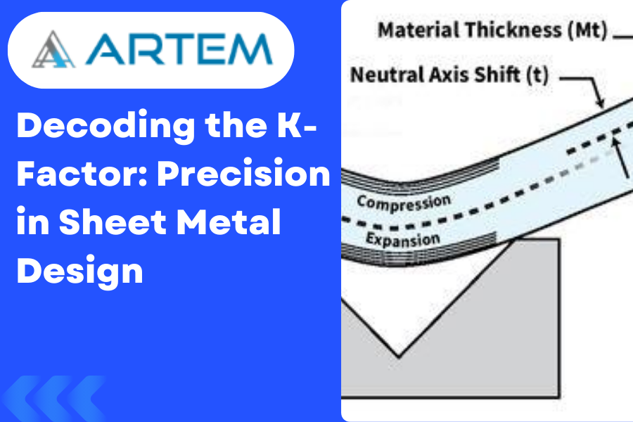
Welcome to the intricate world of sheet metal design, where precision is paramount, and every bend matters. In this blog, we’ll unravel the mystery behind a key player in sheet metal formulation: the K-Factor. Let’s explore what the K-Factor is, its significance in sheet metal bending, and how it dances in harmony with different materials. Understanding the K-Factor The K-Factor, short for “neutral axis factor” or “bend allowance factor,” is a critical parameter in sheet metal bending. It’s a dimensionless value that represents the ratio of the neutral axis location to the material thickness. In simpler terms, the K-Factor helps account for the material’s behavior during bending, ensuring accurate calculations for the flat pattern. The K-Factor Formula: A Glimpse into the Math The formula for calculating the K-Factor is: This distance is typically measured from the center of the material thickness to the neutral axis, where no stretching or compressing occurs during bending. Significance of K-Factor in Sheet Metal Bending Accurate Bend Allowance: The K-Factor plays a pivotal role in determining the bend allowance, which, in turn, influences the flat pattern’s accuracy. It helps adjust for the material’s stretching or compressing during the bending process. Material Behavior Consideration: Different materials exhibit varying behaviors during bending. The K-Factor provides a way to tailor the bending calculations to the specific characteristics of the material being used. Precision in Design: Achieving precision in sheet metal design is not just about angles and dimensions; it’s about understanding how the material responds to bending forces. The K-Factor ensures that your design aligns with the real-world behavior of the material. K-Factor and Material Relationship: A Symbiotic Dance The K-Factor is intricately linked to the material properties of the sheet metal being used. Different materials have distinct behaviors during bending, and the K-Factor allows designers to account for these variations. Here’s how the relationship unfolds: Material Ductility: Ductility, the ability of a material to undergo deformation without rupture or cracking, influences how the material stretches during bending. Materials with higher ductility might have different K-Factors compared to less ductile ones. Material Thickness: The thickness of the sheet metal also affects the bending process. Thicker materials may have different K-Factors compared to thinner ones, as the forces exerted during bending vary with thickness. Bend Radius: The radius of the bend significantly impacts the K-Factor. Different bend radii can result in variations in the stretching or compressing of the material, influencing the appropriate K-Factor to use. Conclusion: Mastering the Material Symphony In the realm of sheet metal design, the K-Factor is your guide to mastering the material symphony. It ensures that your designs are not just lines on paper but accurate representations of how the material will behave in the real world. As you delve into the world of sheet metal bending, remember that the K-Factor is your ally, helping you achieve precision, accuracy, and a harmonious dance between design and material reality. Happy bending!

Verifying and validating a model developed in NX or CATIA is a crucial step to ensure that the design meets the specified requirements and adheres to industry standards. The verification process focuses on checking the model for accuracy, while validation ensures that the model aligns with the intended functionality and performance. Here’s a guide on how to perform verification and validation in NX or CATIA. VERIFICATION STEPS 1.Geometry Checks: NX: Utilize tools like “Check-Mate” to verify the geometric integrity of your model. Run geometry analysis tools to ensure there are no gaps, overlaps, or inconsistencies in the geometry. CATIA: Use the “Healing Assistant” to repair any geometric issues. Employ the “Geometrical Set” feature to organize and check geometry. 2.Dimensional Checks: NX: Inspect and validate dimensions using the “Inspect” or “Measure” tools. Ensure that dimensions meet the specified tolerances. CATIA: Utilize the “Measurement” and “Dimension” tools to verify dimensions. Check that dimensions conform to the design requirements. 3. Interference Checks: NX: Use the “Interference Analysis” tool to detect and resolve interference issues. Ensure that components do not interfere with each other during operation. CATIA: Employ the “Clash Detection” tool to identify interference. Validate that there are no clashes between components. 4. Assembly Checks: NX: Verify assembly constraints and relationships using the “Assembly Navigator.” Ensure that parts are correctly positioned and connected in the assembly. CATIA: Use the “Assembly Design” workbench to validate assembly constraints. Confirm that the assembly functions as intended. VALIDATION STEPS 1. Simulation and Analysis: NX: Utilize the simulation capabilities to analyze structural, thermal, or fluid behavior. Validate that the model performs as expected under different conditions. CATIA: Leverage simulation tools for structural, thermal, or fluid analysis. Validate the model’s performance against design requirements. 2. Prototyping and Testing: NX: If applicable, use NX for generating prototypes through additive manufacturing or traditional methods. Conduct physical testing to validate the model’s real-world behavior. CATIA: CATIA provides capabilities for generating prototypes and simulations for testing. Validate the physical prototype against the virtual model. 3. Collaborative Design Review: NX: Use the “Teamcenter” integration for collaborative design reviews and feedback. Ensure that all stakeholders are aligned on the design requirements. CATIA: Leverage collaborative design environments for multidisciplinary reviews. Incorporate feedback to refine and validate the design. 4. Compliance with Standards: Ensure that the model complies with industry standards, such as ISO, ASME, or specific customer standards. Validate that the design meets regulatory requirements for the intended application. DOCUMENTION 1. Design Documentation: Create comprehensive design documentation that includes drawings, specifications, and design intent. Ensure that the documentation accurately reflects the verified and validated design. 2. Change Management: Implement a robust change management process to track and document any modifications to the design. Validate that changes align with the initial design requirements. 1. Table for NX and CATIA in view of Verification Steps : Verification Steps NX CATIA Geometry Checks – Use “Check-Mate” and geometry analysis tools. – Utilize “Healing Assistant” and geometry checking tools. Dimensional Checks – Inspect and validate dimensions using “Inspect” or “Measure” tools. – Use “Measurement” and “Dimension” tools for verification. Interference Checks – Use “Interference Analysis” to detect and resolve interference. – Employ “Clash Detection” for identifying interferences. Assembly Checks – Verify constraints and relationships using “Assembly Navigator.” – Use “Assembly Design” workbench to validate constraints. 2.Table for NX and CATIA in view of Validation steps: Validation Steps NX CATIA Simulation and Analysis – Utilize simulation for structural, thermal, and fluid analysis. – Leverage simulation tools for structural, thermal, and fluid analysis. Prototyping and Testing – Generate prototypes through additive manufacturing or traditional methods. – Use CATIA for generating prototypes and simulations for testing. Collaborative Design Review – Use “Teamcenter” integration for collaborative reviews and feedback. – Leverage collaborative design environments for multidisciplinary reviews. Compliance with Standards – Ensure compliance with industry standards and regulatory requirements. – Validate compliance with industry standards and regulatory requirements. 3.Table for NX and CATIA in view of Documentation : Documentation NX CATIA Design Documentation – Create comprehensive design documentation with drawings and specifications. – Develop detailed design documentation with drawings and specifications. Change Management – Implement a robust change management process to track modifications. – Ensure a robust change management process to track and document changes. Conclusion: Ensuring Excellence in Design Verifying and validating a model in NX or CATIA is an iterative and comprehensive process that involves both digital analysis and real-world testing. By systematically checking geometry, dimensions, interferences, and assembly, and then validating through simulation, prototyping, and collaborative design reviews, you ensure the excellence of your design. The documentation and change management steps add a layer of control and traceability, ensuring that the design remains aligned with requirements throughout its lifecycle.

Welcome to our NX CAD journey! In this blog post, we’ll guide you through a checklist to ensure you master the art of 2D sketching and 3D modeling. Whether you’re a beginner or looking to enhance your skills, these steps will help you create precise and efficient designs using Siemens NX CAD software. 2D Sketching Checklist 1. Understand the Basics Familiarize yourself with the user interface. Learn the essential tools: lines, circles, arcs, constraints, etc. 2. Create a Solid Foundation Start with accurate reference geometry. Utilize layers to organize and manage your sketch elements. 3. Use Constraints Effectively Apply geometric and dimensional constraints for stability. Learn how to use constraints to control sketch behavior. 4. Explore Advanced Sketching Techniques Master splines, ellipses, and other advanced sketch entities. Experiment with sketch patterns for efficient design replication. 5. Check for Sketch Quality Regularly inspect and optimize your sketches. Use the sketch doctor tool to identify and fix potential issues. 6. Incorporate Parametric Design Understand the power of parametric relationships. Practice modifying dimensions and constraints to observe design changes. 3D Modeling Checklist 1. Start with a Solid Foundation Transition smoothly from 2D sketches to 3D models. Understand the importance of datum planes and coordinate systems. 2. Master Extrusions and Revolutions Learn to create extrusions and revolved features. Experiment with different options and settings. 3. Utilize Advanced Modeling Tools Explore sweeps, lofts, and blends for complex shapes. Understand how to use Boolean operations effectively. 4. Harness the Power of Assemblies Grasp the basics of assembly creation. Understand how to constrain components within an assembly. 5. Optimize Your Workflow Learn keyboard shortcuts for faster modeling. Utilize the feature tree for efficient design history navigation. 6. Ensure Model Accuracy Regularly check and validate your model’s accuracy. Utilize analysis tools to ensure the structural integrity of your designs. Conclusion By following this comprehensive checklist, you’ll be well on your way to mastering 2D sketching and 3D modeling in NX CAD. Remember, practice is key, so don’t hesitate to experiment with different features and functionalities. Happy designing!
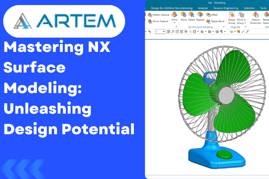
Welcome to our exploration of Surface Modeling in NX, where we unravel the intricate world of creating complex shapes and designs. Surface modeling is an integral part of computer-aided design (CAD) that allows engineers and designers to craft aesthetically pleasing and functionally efficient products. Let’s dive into the depth of NX’s surface modeling capabilities. Understanding Surface Modeling Surface modeling involves creating 3D shapes using interconnected surfaces rather than solid volumes. This technique is particularly useful when dealing with intricate designs, ergonomic considerations, or the need for smooth transitions between shapes. NX Surface Modeling Options: 1 Curve Creation: Spline Curves: Start your surface modeling journey by mastering the creation of spline curves. These smooth, continuous curves are essential for creating organic shapes. Section Curves: Learn to use section curves for precise control over the shape of your surfaces. These curves define the profiles that shape your surfaces. 2. Surface Creation: Extrude and Revolve Surfaces: Begin with the basics. Extrude and revolve surface creation tools allow you to extend and rotate 2D profiles to form 3D surfaces. Blend and Sweep Surfaces: Explore the blend and sweep options for creating complex transitions and blends between different surface sections. 3. Advanced Surface Operations: Extend and Trim Surfaces: Refine your surfaces by extending or trimming them to meet specific design requirements. Offset Surfaces: Create offset surfaces for generating parallel or concentric surfaces with controlled distances 4. Surface Editing: Move and Edit Surface Points: Gain control over your surfaces by moving and editing surface points to achieve the desired shape. Global Surface Editing: Utilize advanced editing tools to globally modify surfaces and maintain design intent. 5. Surface Analysis and Validation: Curvature Analysis: Evaluate the quality of your surfaces using curvature analysis tools. Ensure smooth transitions and avoid undesirable surface anomalies. Surface Validation: Employ validation tools to check for gaps, overlaps, or other issues in your surface model. 6. Hybrid Modeling: Combine with Solid Modeling: Integrate your surface models seamlessly with solid modeling for a hybrid approach, allowing the best of both worlds. 7. Documentation and Export: Detailing and Annotation: Add detailing and annotations to your surface models to create comprehensive manufacturing documentation. Export Options: Familiarize yourself with various export options to share your surface models with other CAD systems or stakeholders. Conclusion: Surface modeling in NX opens up a realm of possibilities for designers and engineers. By mastering the diverse set of tools and techniques available, you can bring your most ambitious designs to life. Remember, practice and experimentation are key to becoming proficient in surface modeling. Happy modeling!
Online AUTOCAD Course in India AutoCAD is a software that has revolutionized the field of design. It is one of the leading software in 3D designing, 2D drafting and detailing projects in a number of industries. What is AutoCAD? AutoCAD is a computer-aided design (CAD) software application used for creating 2D and 3D designs. AutoCAD was developed by Autodesk in 1982 and has become one of the most widely used CAD programs. The software can be used for a variety of purposes, such as creating electrical schematics, designing buildings, or creating mechanical parts. AutoCAD is a powerful tool that can help you create precise 2D and 3D designs. The software is easy to use and has a wide range of features that make it suitable for a variety of design tasks. If you’re looking to learn AutoCAD, our online course is the perfect way to get started. Why Choose an Online Course? There are many reasons to choose an online AUTOCAD course in India. One reason is that it is more convenient than a traditional classroom setting. You can access the course material at any time and from any location with an internet connection. Another reason to choose an online course is that you can usually complete the course at your own pace. This means that you can take as much or as little time as you need to complete the assignments and learn the material. This can be especially helpful if you have a busy work or home life. Lastly, many online courses offer a variety of interactive features that can make learning more fun and engaging. For example, some courses include video lectures, while others offer forums where you can discuss course material with other students. Online AUTOCAD Course in India: Benefits of Our AutoCAD Courses Learn from Experienced Professionals: All of our AutoCAD courses are taught by experienced professionals who have years of experience using the software. This means that you’ll be able to learn from their wealth of knowledge and get the most out of your training. Get Hands-on Experience: One of the best ways to learn AutoCAD is by getting hands-on experience with the software. With our courses, you’ll be able to work on real-world projects and gain valuable practical experience. Affordable and Flexible: Our courses are very affordable, especially when compared to traditional classroom-based training. They are also flexible, so you can study at your own pace and in your own time. Industry Recognized Certification: Upon completion of our courses, you’ll receive an industry recognized certification which will help you to advance your career. What You Will Be Learning in the Course? In this online AUTOCAD course in India, you will be learning about the different features and functions of the software. You will also be learning how to create 2D and 3D designs using the software. The course will also teach you how to use the software to create drawings for engineering, architectural, and other purposes. Best Place to Take Your AutoCAD Course! There are a few things to consider when choosing the best place to take your AutoCAD course. Depending on your level of experience and knowledge, you may want to consider a course that is offered by a certified AutoCAD instructor. These instructors typically have years of experience and can offer you one-on-one attention, as well as a wealth of information. Additionally, many colleges and universities now offer AutoCAD courses online. These courses are often more affordable than those offered in person, and they provide you with the flexibility to complete the course at your own pace. If you’re considering an online course, be sure to research the quality of the course and the reputation of the provider before enrolling. Finally, if you know someone who has recently taken an AutoCAD course, ask for their recommendation. They may be able to point you in the direction of a great instructor or tell you about an online course that they found especially helpful. What are the eligibility of AutoCAD course? Anyone can join the course from diploma, graduate & post-graduation. There is no pre-requisite for the AutoCAD course. In order to be eligible for the AutoCAD course, you must have a basic understanding of computers and their operations. This course is not meant for beginners. You should also have a basic knowledge of drafting and engineering principles. If you have these skills, then you will be able to get the most out of the course.
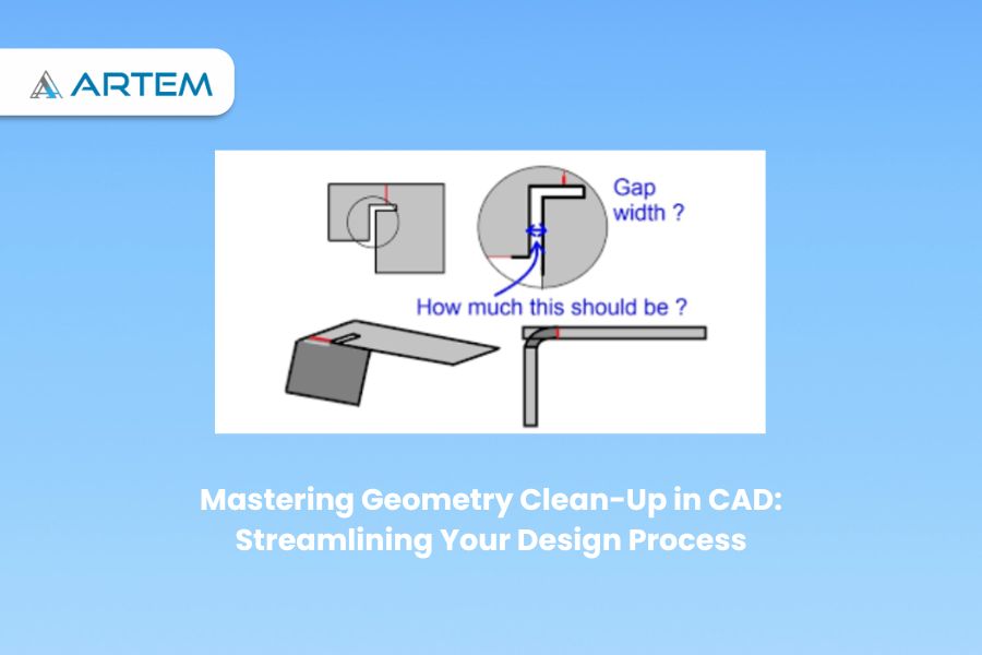
Geometry clean-up is of utmost importance in the field of computer-aided design (CAD) as it ensures the accuracy, efficiency, and reliability of the models created. Cleaning up the geometry involves removing errors, inconsistencies, and unnecessary complexity from the CAD model. By doing so, engineers and designers can have confidence in the accuracy of their designs, leading to better outcomes in various applications. One key importance of geometry clean-up is its impact on design accuracy. Clean geometry ensures that the CAD model faithfully represents the intended design, free from errors and gaps that could compromise its integrity. This accuracy is crucial for precise measurements, analysis, and simulation, as well as effective communication with stakeholders. Here are some general steps to perform geometry clean-up in CAD: Identify Issues: Carefully examine the model to identify any geometric issues, such as gaps, overlaps, self-intersections, duplicate entities, or small sliver surfaces. Use visualization tools and analysis features in your CAD software to aid in identifying problematic areas. Gap and Overlap Removal: Address any gaps or overlaps between entities by using appropriate CAD tools. This may involve adjusting dimensions, extending or trimming entities, or using commands like filleting or chamfering to blend and connect surfaces or edges. Remove Duplicate Geometry: Identify and delete any duplicate entities such as lines, curves, or surfaces. These duplicates can cause issues during subsequent operations or analyses. Healing and Repairing Surfaces: If the model contains surface imperfections or errors, use CAD tools for surface healing and repairing. These tools can analyze and fix issues like self-intersecting surfaces, non-manifold edges, or irregularities in surface normal. Correct Small Edges and Faces: Identify and delete small edges or faces that might result from numerical inaccuracies or errors during the modeling process. These small entities can cause problems during meshing or further processing. Simplify Complex Geometry: Analyze the model for complex or intricate details that are not essential for the desired outcome. Simplify or remove unnecessary features to reduce model complexity and improve computational efficiency. Merge Coincident Entities: Identify entities that are coincident or very close to each other and merge them into a single entity. This process helps eliminate redundant entities and improves the model’s clarity and simplicity. Remove Duplicates: Identify and eliminate duplicate or redundant entities such as points, lines, or surfaces. Use CAD commands like merge, join, or remove duplicates to consolidate the model and reduce unnecessary complexity. Check and Correct Normals: Verify that the normals (direction vectors perpendicular to the surface) of the model’s faces are consistent and pointing in the desired direction. Inconsistent or inverted normals can cause issues in rendering, analysis, or manufacturing processes. Repair Self-Intersections: Detect and resolve any self-intersections within the model, where surfaces or solid bodies intersect with themselves. These intersections can cause problems during simulation or manufacturing, and need to be resolved. Edge and Face Cleanup: Inspect the model for inconsistent or unnecessary edges or faces. Delete or merge redundant edges, remove unwanted internal features, and ensure smooth and continuous surfaces. Feature Verification: Validate important geometric features and dimensions to ensure they meet design requirements. Use measurement and analysis tools in your CAD software to verify dimensions, tolerances, angles, and other critical features. Optimize Topology: Analyze the model’s topology and rework it if necessary to improve efficiency, accuracy, or performance. This step involves assessing the connectivity and arrangement of the model’s components and modifying them as needed. Validate Model Integrity: Use built-in CAD tools or specialized software to perform integrity checks on the model, looking for errors such as open edges, non-manifold geometry, or invalid entities. Address any identified issues to ensure a clean and error-free model. Document the Cleaning Process: Keep a record of the cleaning steps performed on the CAD model, including any modifications or repairs made. This documentation aids in maintaining traceability and provides a reference for future modifications or troubleshooting. By following these steps, engineers and designers can ensure that the CAD geometry is clean, accurate, and ready for further operations such as analysis, simulation, or manufacturing. Simulation and Analysis Accuracy: Accurate geometry is crucial for reliable simulation and analysis results. Any inaccuracies or inconsistencies in the geometry can propagate and affect the accuracy of simulations or analyses. Cleaning up the geometry ensures that the model provides a solid foundation for obtaining accurate results. Manufacturing Readiness: Clean geometry is essential for manufacturing processes. When transferring the CAD model to manufacturing software or physical production, clean geometry ensures that the design is ready for manufacturing. It reduces the likelihood of errors, such as misinterpretations or difficulties in translating the design into a physical product. Collaboration and Communication: Clean geometry facilitates effective collaboration and communication among team members and stakeholders. It improves the clarity of the design, making it easier to understand and review. Clean geometry helps ensure that everyone involved in the project has a clear and accurate representation of the design intent. Data Interoperability: Clean geometry enhances data interoperability between different CAD systems and engineering tools. When sharing or exchanging CAD models, clean geometry reduces the chances of data loss or compatibility issues. It ensures that the model can be seamlessly integrated into different workflows and software environments. In summary, cleaning up CAD geometry is essential to ensure design accuracy, optimize modeling efficiency, avoid errors, obtain accurate simulation results, prepare for manufacturing, facilitate collaboration, and enable data interoperability. It plays a critical role in maintaining the integrity and reliability of the design throughout the entire product development process. As mentioned, clean-up geometry plays a significant role in manufacturing readiness. It ensures that the CAD model can be seamlessly translated into physical production, reducing the risk of errors or difficulties in manufacturing processes such as machining or 3D printing. Clean geometry promotes smooth data transfer and compatibility, contributing to efficient and high-quality manufacturing outcomes. If you’re interested in improving your CAD skills and learning more about geometry clean-up, you may consider exploring CAD courses such as NX Semens, Solidworks, CATIA and so on. One notable online platform that offers CAD courses