

Welcome to the fascinating realm of sheet metal formulation, where precision meets creativity. Mastering the formulas involved in sheet metal design is like uncovering the language of a skilled craftsman. In this blog, we’ll delve into the essential formulas that underpin the art of sheet metal work, providing you with the knowledge to craft your designs with accuracy and finesse. 1.Understanding Sheet Metal Thickness (T) The thickness of a sheet metal piece is a fundamental parameter in any design. It dictates the material’s strength, weight, and overall structural integrity. Formula: Thickness T= Weight of the sheet Surface Area of the sheet Example: If you have a sheet metal piece weighing 10 pounds with a surface area of 5 square feet, the thickness (T) would be 10/5=2 pounds per square foot. 2.Calculating Bend Allowance (BA) Bend allowance is a crucial factor in determining the flat pattern length before bending. It considers the material’s elasticity during the bending process. Formula:Bend Allowance (BA)=180 ×Bend Angle ×Radius+K-factor ×Material Thickness Example: For a 90-degree bend with a radius of 1 inch, a material thickness of 0.05 inches, and a K-factor of 0.33, the bend allowance (BA) would be calculated using the formula. 3.Determining Bend Deduction (BD) Bend deduction accounts for the stretching of material on the outer surface of a bend and is crucial for accurate flat pattern development. Formula:Bend Deducation BD= Bend Allowance BA-Material Thickness × 180 ×Bend Angle Example: Using the values from the previous example, the bend deduction (BD) can be calculated. 4.Calculating Developed Length (DL) Developed length is the length of the sheet metal required for a specific design, considering bends and their allowances. Formula:Developed Length DL=Sum of All Flat Lenghts+Bend Allwances (BA) Example: If you have a flat pattern length of 10 inches with multiple bends, each with its bend allowance, the developed length (DL) is calculated by summing these lengths. 5.Determining Hole Patterns: Equally Spaced Holes In sheet metal design, equally spaced holes are a common feature. Calculating their positions ensures uniformity and precision. Formula:Distance Between Holes= Lemgth of SheetNumber of Holes-1 Example: For a sheet metal piece with a length of 20 inches and four equally spaced holes, the distance between holes is calculated using the formula. 6.Bend Radius: The bending radius is the minimum curvature a material can endure during the bending process without causing undue stress, deformation, or damage. Formula:Bend Radius R= Material Thickness ×Bend Factor Example: Imagine you’re working with a sheet of stainless steel with a thickness of 1.5 mm. If the bend factor for stainless steel is 0.016, the bend radius would be 1.5 mm x 0.016 = 0.024 mm. 7.K-Factor: The K-factor in sheet metal design represents the ratio of the neutral axis location to the material thickness, crucial for accurate bend allowance calculations during manufacturing. Formula:K-factor k= inside Radius-Material Thickness 2 ×Material Thickness Example: Let’s say you have a sheet metal part with an inside radius of 3 mm and a material thickness of 2 mm. The K-factor would be (3 mm – 2 mm) / (2 x 2 mm) = 0.25. 8.Flat Pattern Length: Flat pattern length is the total length of a 2D sheet metal pattern, accounting for all bends and features, crucial for material layout and manufacturing. Formula:Flat Pattern Length=Bend Allowance ×Bend Angles Example: For a sheet metal part with a bend allowance of 5 mm and three 90-degree bends, the flat pattern length would be 5 mm x 3 = 15 mm. 9.Setback: Setback is the distance from the bend line to the innermost surface of the material after bending, crucial for accurate flat pattern development. Formula:Setback=0.33 ×Material Thickness Example: For a sheet metal part with a material thickness of 1.2 mm, the setback would be 0.33 x 1.2 mm = 0.396 mm. 10.Hem Allowance: Hem allowance is an additional material provided along the edge of a sheet metal component to create a folded, reinforced, or aesthetically finished edge. Formula:Hem Allowance =2×Material Thickness Example: If you’re creating a hem on a sheet metal part with a material thickness of 1.5 mm, the hem allowance would be 2 x 1.5 mm = 3 mm. 11.Deciphering Minimum Flange Widths Determining the minimum flange width ensures that the material can withstand bending processes without deformation or failure. Formula for Minimum Flange Width (b):Minimum Flange Thickness=2 ×Material Thickness Example: Let’s consider a sheet metal component with a thickness (t) of 1.5 mm. Using the formula, the minimum flange width (b) would be 2×1.5=32×1.5=3 mm. Formula for Minimum Hole Diameter (D):Minimum Hole Diameter=2×Material Thickness+Hole Clearance Example: For a sheet metal material with a thickness (t) of 2 mm, the minimum hole diameter (D) would be 2×2+1.2=5.22×2+1.2=5.2 mm. 12.Navigating Blank Diameters for Drawing Precision Blank diameters determine the size of the initial flat pattern before bending, influencing the overall success of the sheet metal forming process. Formula for Blank Diameter (BD):Blank Diameter=Developed Length of part+K-factor ×Inside bend Radius Example: Consider a sheet metal part with a developed length (L) of 150 mm, a K-factor (K) of 0.33, and an inside bend radius (R) of 5 mm. The blank diameter (BD) would be 150+0.33×5=151.65150+0.33×5=151.65 mm. Conclusion: Crafting with Precision and Knowledge Armed with these formulas, you now possess the tools to navigate the intricate world of sheet metal formulation. Whether you’re calculating thickness, allowances for bends, or developing the perfect hole pattern, these formulas are your guide to crafting with precision and knowledge. Embrace the artistry of sheet metal work, and let these formulas be your companions in every design endeavor. Always consult relevant standards and guidelines for accurate calculations in specific scenarios. Happy crafting!
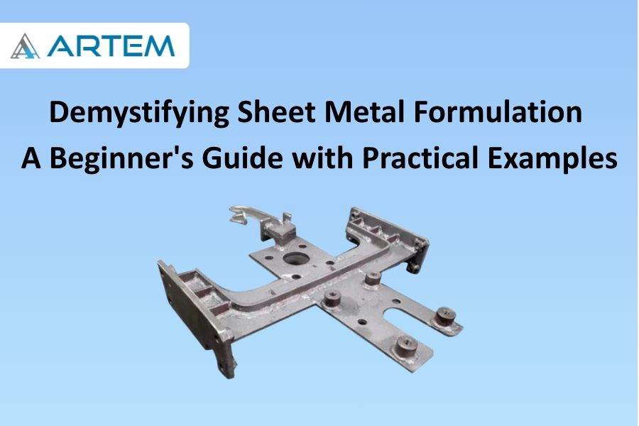
Welcome to the world of sheet metal formulation, where flat sheets transform into intricate structures with the precision of a craftsman’s hands. Whether you’re an aspiring engineer or a DIY enthusiast, understanding the basics of sheet metal formulation is a fundamental step toward bringing your designs to life. In this blog, we’ll unravel the essential concepts and techniques, using practical examples to guide you through the process. The Raw Material: Types of Sheet Metal Before we dive into the formulation process, let’s familiarize ourselves with the raw material. Common sheet metal materials include steel, aluminum, and stainless steel. Each material has its unique properties, influencing factors such as strength, weight, and corrosion resistance. Example: If you’re designing a lightweight panel for an enclosure, aluminum might be a suitable choice due to its low density and corrosion-resistant nature. Getting Started: Basics of Sheet Metal Formulation 2.1 Blank Development: Unfolding the Sheet The first step in sheet metal formulation is the development of a blank, which is the flat pattern of the final 3D shape. This process involves unfolding the sheet metal to create a 2D representation that can be cut and bent. Example: Let’s say you’re designing a simple rectangular box. The blank development involves unfolding the sheet to create a flat pattern that, when bent and assembled, will result in the box shape. 2.2 Bending: Shaping the Material Bending is a critical aspect of sheet metal formulation. It involves deforming the sheet metal along a straight axis to create angles or curves, bringing the flat pattern into its 3D form. Example: Continuing with our rectangular box example, the bending process would involve folding the flat pattern along predefined lines to create the box’s sides and edges. Advanced Techniques: Adding Features to Your Design 3.1 Flanges: Extending the Design Flanges are extensions of the sheet metal that add depth to the structure. They can be simple bends or more complex shapes, allowing you to create features such as tabs or reinforcement. Example: In our box design, adding flanges could involve extending certain edges to create a lip or reinforcement for added strength. 3.2 Holes and Cutouts: Modifying the Material Introducing holes and cutouts is a common practice in sheet metal design. These features not only reduce weight but also serve functional purposes, such as allowing ventilation or accommodating fasteners. Example: You might add ventilation holes to the sides of your box design or cutouts for screws to assemble the components. Putting It All Together: Assembling Sheet Metal Components Once you’ve mastered the individual components, the final step is assembly. Understanding how different sheet metal parts come together ensures a seamless and functional end product. Example: Taking our box design, assembly would involve aligning the edges and fastening the components, creating a solid and well-constructed box. Here’s the information presented in a tabular form for easy reference: Aspect Explanation Example Raw Material Common sheet metal materials include steel, aluminum, and stainless steel. Choosing aluminum for a lightweight panel in an enclosure. Blank Development Unfolding the sheet to create a 2D representation for cutting and bending. Creating a flat pattern for a rectangular box design. Bending Deforming the sheet metal along a straight axis to create angles or curves. Folding the flat pattern along predefined lines for the box. Flanges Extensions adding depth to the structure, creating features like tabs or reinforcement. Extending certain edges to create a lip in the box design. Holes and Cutouts Introducing features for reducing weight and serving functional purposes. Adding ventilation holes or cutouts for screws in the box. Assembly Aligning edges and fastening components to create a solid and well-constructed product. Assembling the different parts of the box design. Conclusion: Crafting with Precision Sheet metal formulation is a captivating journey where creativity meets precision. As you venture into creating your own sheet metal designs, remember the basics: unfolding the sheet, shaping it through bending, and adding features to enhance functionality. With these foundational skills, you’ll soon find yourself crafting a variety of sheet metal structures with confidence and precision. Happy formulating!

Welcome to the intricate world of sheet metal design, where precision is paramount, and every bend matters. In this blog, we’ll unravel the mystery behind a key player in sheet metal formulation: the K-Factor. Let’s explore what the K-Factor is, its significance in sheet metal bending, and how it dances in harmony with different materials. Understanding the K-Factor The K-Factor, short for “neutral axis factor” or “bend allowance factor,” is a critical parameter in sheet metal bending. It’s a dimensionless value that represents the ratio of the neutral axis location to the material thickness. In simpler terms, the K-Factor helps account for the material’s behavior during bending, ensuring accurate calculations for the flat pattern. The K-Factor Formula: A Glimpse into the Math The formula for calculating the K-Factor is: This distance is typically measured from the center of the material thickness to the neutral axis, where no stretching or compressing occurs during bending. Significance of K-Factor in Sheet Metal Bending Accurate Bend Allowance: The K-Factor plays a pivotal role in determining the bend allowance, which, in turn, influences the flat pattern’s accuracy. It helps adjust for the material’s stretching or compressing during the bending process. Material Behavior Consideration: Different materials exhibit varying behaviors during bending. The K-Factor provides a way to tailor the bending calculations to the specific characteristics of the material being used. Precision in Design: Achieving precision in sheet metal design is not just about angles and dimensions; it’s about understanding how the material responds to bending forces. The K-Factor ensures that your design aligns with the real-world behavior of the material. K-Factor and Material Relationship: A Symbiotic Dance The K-Factor is intricately linked to the material properties of the sheet metal being used. Different materials have distinct behaviors during bending, and the K-Factor allows designers to account for these variations. Here’s how the relationship unfolds: Material Ductility: Ductility, the ability of a material to undergo deformation without rupture or cracking, influences how the material stretches during bending. Materials with higher ductility might have different K-Factors compared to less ductile ones. Material Thickness: The thickness of the sheet metal also affects the bending process. Thicker materials may have different K-Factors compared to thinner ones, as the forces exerted during bending vary with thickness. Bend Radius: The radius of the bend significantly impacts the K-Factor. Different bend radii can result in variations in the stretching or compressing of the material, influencing the appropriate K-Factor to use. Conclusion: Mastering the Material Symphony In the realm of sheet metal design, the K-Factor is your guide to mastering the material symphony. It ensures that your designs are not just lines on paper but accurate representations of how the material will behave in the real world. As you delve into the world of sheet metal bending, remember that the K-Factor is your ally, helping you achieve precision, accuracy, and a harmonious dance between design and material reality. Happy bending!
Welcome to the world of sheet metal formulation, where flat sheets transform into intricate structures with the precision of a craftsman’s hands. Whether you’re an aspiring engineer or a DIY enthusiast, understanding the basics of sheet metal formulation is a fundamental step toward bringing your designs to life. In this blog, we’ll unravel the essential concepts and techniques, using practical examples to guide you through the process. The Raw Material: Types of Sheet Metal Before we dive into the formulation process, let’s familiarize ourselves with the raw material. Common sheet metal materials include steel, aluminum, and stainless steel. Each material has its unique properties, influencing factors such as strength, weight, and corrosion resistance. Example: If you’re designing a lightweight panel for an enclosure, aluminum might be a suitable choice due to its low density and corrosion-resistant nature. Getting Started: Basics of Sheet Metal Formulation 2.1 Blank Development: Unfolding the Sheet The first step in sheet metal formulation is the development of a blank, which is the flat pattern of the final 3D shape. This process involves unfolding the sheet metal to create a 2D representation that can be cut and bent. Example: Let’s say you’re designing a simple rectangular box. The blank development involves unfolding the sheet to create a flat pattern that, when bent and assembled, will result in the box shape. 2.2 Bending: Shaping the Material Bending is a critical aspect of sheet metal formulation. It involves deforming the sheet metal along a straight axis to create angles or curves, bringing the flat pattern into its 3D form. Example: Continuing with our rectangular box example, the bending process would involve folding the flat pattern along predefined lines to create the box’s sides and edges. Advanced Techniques: Adding Features to Your Design 3.1 Flanges: Extending the Design Flanges are extensions of the sheet metal that add depth to the structure. They can be simple bends or more complex shapes, allowing you to create features such as tabs or reinforcement. Example: In our box design, adding flanges could involve extending certain edges to create a lip or reinforcement for added strength. 3.2 Holes and Cutouts: Modifying the Material Introducing holes and cutouts is a common practice in sheet metal design. These features not only reduce weight but also serve functional purposes, such as allowing ventilation or accommodating fasteners. Example: You might add ventilation holes to the sides of your box design or cutouts for screws to assemble the components. Putting It All Together: Assembling Sheet Metal Components Once you’ve mastered the individual components, the final step is assembly. Understanding how different sheet metal parts come together ensures a seamless and functional end product. Example: Taking our box design, assembly would involve aligning the edges and fastening the components, creating a solid and well-constructed box. Here’s the information presented in a tabular form for easy reference: Aspect Explanation Example Raw Material Common sheet metal materials include steel, aluminum, and stainless steel. Choosing aluminum for a lightweight panel in an enclosure. Blank Development Unfolding the sheet to create a 2D representation for cutting and bending. Creating a flat pattern for a rectangular box design. Bending Deforming the sheet metal along a straight axis to create angles or curves. Folding the flat pattern along predefined lines for the box. Flanges Extensions adding depth to the structure, creating features like tabs or reinforcement. Extending certain edges to create a lip in the box design. Holes and Cutouts Introducing features for reducing weight and serving functional purposes. Adding ventilation holes or cutouts for screws in the box. Assembly Aligning edges and fastening components to create a solid and well-constructed product. Assembling the different parts of the box design. Conclusion: Crafting with Precision Sheet metal formulation is a captivating journey where creativity meets precision. As you venture into creating your own sheet metal designs, remember the basics: unfolding the sheet, shaping it through bending, and adding features to enhance functionality. With these foundational skills, you’ll soon find yourself crafting a variety of sheet metal structures with confidence and precision. Happy formulating!

Welcome to the fascinating realm of sheet metal formulation, where precision meets creativity. Mastering the formulas involved in sheet metal design is like uncovering the language of a skilled craftsman. In this blog, we’ll delve into the essential formulas that underpin the art of sheet metal work, providing you with the knowledge to craft your designs with accuracy and finesse. 1. Understanding Sheet Metal Thickness (T) The thickness of a sheet metal piece is a fundamental parameter in any design. It dictates the material’s strength, weight, and overall structural integrity. Formula: Thickness T= Weight of the sheet Surface Area of the sheet Example: If you have a sheet metal piece weighing 10 pounds with a surface area of 5 square feet, the thickness (T) would be 10/5=2 pounds per square foot. 2. Calculating Bend Allowance (BA) Bend allowance is a crucial factor in determining the flat pattern length before bending. It considers the material’s elasticity during the bending process. Formula: Bend Allowance (BA)=180 ×Bend Angle ×Radius+K-factor ×Material Thickness Example: For a 90-degree bend with a radius of 1 inch, a material thickness of 0.05 inches, and a K-factor of 0.33, the bend allowance (BA) would be calculated using the formula. 3. Determining Bend Deduction (BD) Bend deduction accounts for the stretching of material on the outer surface of a bend and is crucial for accurate flat pattern development. Formula: Bend Deducation BD= Bend Allowance BA-Material Thickness × 180 ×Bend Angle Example: Using the values from the previous example, the bend deduction (BD) can be calculated. 4. Calculating Developed Length (DL) Developed length is the length of the sheet metal required for a specific design, considering bends and their allowances. Formula: Developed Length DL=Sum of All Flat Lenghts+Bend Allwances (BA) Example: If you have a flat pattern length of 10 inches with multiple bends, each with its bend allowance, the developed length (DL) is calculated by summing these lengths. 5. Determining Hole Patterns: Equally Spaced Holes In sheet metal design, equally spaced holes are a common feature. Calculating their positions ensures uniformity and precision. Formula: Distance Between Holes= Lemgth of SheetNumber of Holes-1 Example: For a sheet metal piece with a length of 20 inches and four equally spaced holes, the distance between holes is calculated using the formula. 6. Bend Radius: The bending radius is the minimum curvature a material can endure during the bending process without causing undue stress, deformation, or damage. Formula: Bend Radius R= Material Thickness ×Bend Factor Example: Imagine you’re working with a sheet of stainless steel with a thickness of 1.5 mm. If the bend factor for stainless steel is 0.016, the bend radius would be 1.5 mm x 0.016 = 0.024 mm. 7. K-Factor: The K-factor in sheet metal design represents the ratio of the neutral axis location to the material thickness, crucial for accurate bend allowance calculations during manufacturing. Formula: K-factor k= inside Radius-Material Thickness 2 ×Material Thickness Example: Let’s say you have a sheet metal part with an inside radius of 3 mm and a material thickness of 2 mm. The K-factor would be (3 mm – 2 mm) / (2 x 2 mm) = 0.25. 8. Flat Pattern Length: Flat pattern length is the total length of a 2D sheet metal pattern, accounting for all bends and features, crucial for material layout and manufacturing. Formula: Flat Pattern Length=Bend Allowance ×Bend Angles Example: For a sheet metal part with a bend allowance of 5 mm and three 90-degree bends, the flat pattern length would be 5 mm x 3 = 15 mm. 9. Setback: Setback is the distance from the bend line to the innermost surface of the material after bending, crucial for accurate flat pattern development. Formula: Setback=0.33 ×Material Thickness Example: For a sheet metal part with a material thickness of 1.2 mm, the setback would be 0.33 x 1.2 mm = 0.396 mm. 10. Hem Allowance: Hem allowance is an additional material provided along the edge of a sheet metal component to create a folded, reinforced, or aesthetically finished edge. Formula: Hem Allowance =2×Material Thickness Example: If you’re creating a hem on a sheet metal part with a material thickness of 1.5 mm, the hem allowance would be 2 x 1.5 mm = 3 mm. 11. Deciphering Minimum Flange Widths Determining the minimum flange width ensures that the material can withstand bending processes without deformation or failure. Formula for Minimum Flange Width (b): Minimum Flange Thickness=2 ×Material Thickness Example: Let’s consider a sheet metal component with a thickness (t) of 1.5 mm. Using the formula, the minimum flange width (b) would be 2×1.5=32×1.5=3 mm. Formula for Minimum Hole Diameter (D): Minimum Hole Diameter=2×Material Thickness+Hole Clearance Example: For a sheet metal material with a thickness (t) of 2 mm, the minimum hole diameter (D) would be 2×2+1.2=5.22×2+1.2=5.2 mm. 12.Navigating Blank Diameters for Drawing Precision Blank diameters determine the size of the initial flat pattern before bending, influencing the overall success of the sheet metal forming process. Formula for Blank Diameter (BD): Blank Diameter=Developed Length of part+K-factor ×Inside bend Radius Example: Consider a sheet metal part with a developed length (L) of 150 mm, a K-factor (K) of 0.33, and an inside bend radius (R) of 5 mm. The blank diameter (BD) would be 150+0.33×5=151.65150+0.33×5=151.65 mm. Conclusion: Crafting with Precision and Knowledge Armed with these formulas, you now possess the tools to navigate the intricate world of sheet metal formulation. Whether you’re calculating thickness, allowances for bends, or developing the perfect hole pattern, these formulas are your guide to crafting with precision and knowledge. Embrace the artistry of sheet metal work, and let these formulas be your companions in every design endeavor. Always consult relevant standards and guidelines for accurate calculations in specific scenarios. Happy crafting!
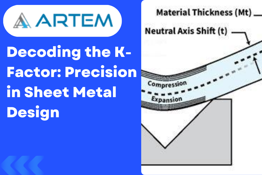
Welcome to the intricate world of sheet metal design, where precision is paramount, and every bend matters. In this blog, we’ll unravel the mystery behind a key player in sheet metal formulation: the K-Factor. Let’s explore what the K-Factor is, its significance in sheet metal bending, and how it dances in harmony with different materials. Understanding the K-Factor The K-Factor, short for “neutral axis factor” or “bend allowance factor,” is a critical parameter in sheet metal bending. It’s a dimensionless value that represents the ratio of the neutral axis location to the material thickness. In simpler terms, the K-Factor helps account for the material’s behavior during bending, ensuring accurate calculations for the flat pattern. The K-Factor Formula: A Glimpse into the Math The formula for calculating the K-Factor is: This distance is typically measured from the center of the material thickness to the neutral axis, where no stretching or compressing occurs during bending. Significance of K-Factor in Sheet Metal Bending Accurate Bend Allowance: The K-Factor plays a pivotal role in determining the bend allowance, which, in turn, influences the flat pattern’s accuracy. It helps adjust for the material’s stretching or compressing during the bending process. Material Behavior Consideration: Different materials exhibit varying behaviors during bending. The K-Factor provides a way to tailor the bending calculations to the specific characteristics of the material being used. Precision in Design: Achieving precision in sheet metal design is not just about angles and dimensions; it’s about understanding how the material responds to bending forces. The K-Factor ensures that your design aligns with the real-world behavior of the material. K-Factor and Material Relationship: A Symbiotic Dance The K-Factor is intricately linked to the material properties of the sheet metal being used. Different materials have distinct behaviors during bending, and the K-Factor allows designers to account for these variations. Here’s how the relationship unfolds: Material Ductility: Ductility, the ability of a material to undergo deformation without rupture or cracking, influences how the material stretches during bending. Materials with higher ductility might have different K-Factors compared to less ductile ones. Material Thickness: The thickness of the sheet metal also affects the bending process. Thicker materials may have different K-Factors compared to thinner ones, as the forces exerted during bending vary with thickness. Bend Radius: The radius of the bend significantly impacts the K-Factor. Different bend radii can result in variations in the stretching or compressing of the material, influencing the appropriate K-Factor to use. Conclusion: Mastering the Material Symphony In the realm of sheet metal design, the K-Factor is your guide to mastering the material symphony. It ensures that your designs are not just lines on paper but accurate representations of how the material will behave in the real world. As you delve into the world of sheet metal bending, remember that the K-Factor is your ally, helping you achieve precision, accuracy, and a harmonious dance between design and material reality. Happy bending!