
When To Use CERIG & RBE3?
In order to simulate the physics of a problem in the mathematics of Ansys, it often becomes unavoidable to associate a set of nodes with a particular behaviour. The reason for such associations may be the assumptions of the basic theory used for the solution algorithm, or, the limitation of Ansys while accepting the actual problem for example Ansys APDL does not provide any direct means to apply torque load. For this kind of application, Ansys provides a special connection called constraint equations. Two automated methods of generating constraint equations are CERIG and RBE3 commands. Although the applications of both the commands traverse the same domain, the basic underlying concept and the way either works are different. In other words, often there is confusion over their use – this blog helps you to know the application and the differences of both the constraint equations. Constraint equations in Ansys are linear, so they are not valid for large-rotation analyses.
CE RIGID REGION
CE rigid are often used to “lump” together portions of the model into rigid regions. The command for CE-based rigid region is CERIG. It defines a rigid region (link, area, or volume) by automatically generating constraint equations to relate nodes in the region. CERIG elements artificially add stiffness by constraining the system to follow a one-to-one linear displacement and/or rotational relationship between the connected nodes. For example, CERIG elements are used to model a wagon wheel type connection between the independent and the dependent nodes.
The procedure for the creation of CERIG is as follows, the user selects one master node, several slave nodes, and the DOF affected. The master node, in this case, means that this is the node that controls the behaviour of the rigid region. Nodes in the rigid region must be assigned a geometric location before this command is used. Also, nodes must be connected to elements having the required degree of freedom set. It means that the ‘master’ node contains the independent DOF and the ‘slave nodes contain the dependent nodes. Generated constraint equations are based on small deflection theory.
CERIG command will generate the constraint equations needed for defining rigid lines in 2-D or 3-D space. Multiple rigid lines relative to a common point are used to define a rigid area or a rigid volume.
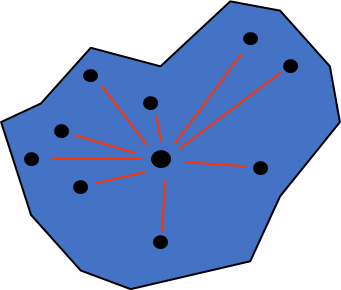
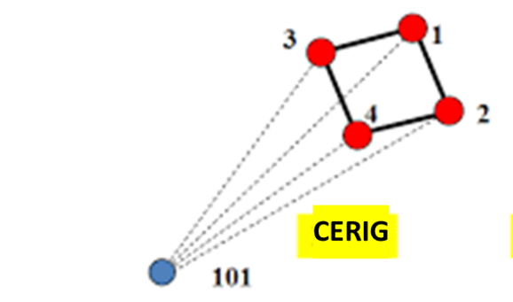
Fig1: Constraint Equation connection and CERIG
Six equations are generated for each pair of constrained nodes in 3-D space. These equations define the six rigid body motions in global Cartesian space. These equations assume that UX, UY, UZ, ROTX, ROTY, and ROTZ degrees of freedom are available at each node.
The UXYZ allows generating a partial set of rigid region equations. This option is useful for transmitting the bending moment between elements having different degrees of freedom at a node. With this option, only two of the three equations are generated for each pair of constrained nodes in 2-D space. In 3-D space, only three of the six equations are generated. In each case, the rotational coupling equations are not generated. Similarly, the RXYZ label allows generating a partial set of equations with the translational coupling equations omitted.
The limitation in the CERIG command is boundary conditions are applied on the ‘master’ node only- boundary conditions conflicting should not be applied to the ‘slave’ nodes.
For example, CERIG elements are used to model a wagon wheel or cycle rim type connection between the independent and the dependent nodes

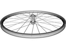
Fig2: Wagon Wheel and Cycle Rim
Second, practical example is – CERIG elements help to simply bolt joint assembly by creating bolts as beam elements and are connected to the flange
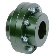
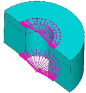
Fig3: Bolted Joint Model assembly and beam as bolt connection with CERIG
CE LOAD – RBE3
RBE3 is used to distribute the load (force/moment) from master to slave nodes. Suppose we are not modeling any component but we need to consider its mass, so in order to consider its weight we will define the mass element and will connect it using RBE3 to the supporting location.
The force is distributed to the slave nodes proportional to the weighting factors. The moment is distributed as forces to the slaves; these forces are proportional to the distance from the center of gravity of the slave nodes times the weighting factors. Only the translational degrees of freedom of the slave nodes are used for constructing the constraint equations. Constraint equations are converted to distributed forces/moments on the slave nodes during the solution.
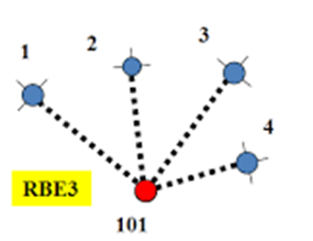
Fig4: RBE3 connection – dependent master node and independent slave nodes
RBE3 on the other hand is not a ‘rigid’ element so to speak. The motion at the ‘dependent’ node is a weighted average of the motion at the ‘independent’ nodes. This is why it is also known as an ‘interpolation’ R element. RBE3 elements do not add artificial stiffness to the structure like CERIG elements do.
By default, the reference node (the single node at the tip of the element) DOF will be the ‘dependent’ DOF. Also, note that the dependent DOF cannot be constrained. They are also not allowed to be part of another RBE element equation.
Another limitation when choosing RBE3 is capable of producing unwanted mechanisms. This can happen if there are insufficient independent DOFs to properly resolve the applied loads and moments for static equilibrium. Hence, care needs to be taken when defining an RBE3 element.
In general, three or more non-colinear ‘independent’ grid points will do the trick for all the DOFs.
The user has the option of inputting two array parameters listing the ‘slave’ nodes and the weighting factors for each ‘slave’ node used for the interpolation of the forces/moments. A force applied on the ‘master’ node is distributed to the ‘slave’ nodes proportional to the weighting factors. A moment applied on the ‘master’ node is distributed as forces to the ‘slave’ nodes which are proportional to the distance from the ‘slave’ nodes times the weighting factors
Its general form is:
Coef1 * DOF1 + Coef2 * DOF2 + Coef3 * DOF3 + … = Constant
Applications related to it are as shown in the figure, for load:
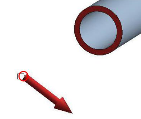
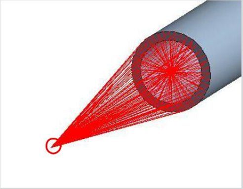
Fig5: RBE3 connection – as a remote force application in ANSYS
Unless you are an expert who really knows what you are doing, it is always recommended you select all DOF for the ‘dependent’ node, but ONLY select the translational DOF for the ‘independent’ nodes.
To variation of CERIG & RBE3 along with the detail difference are noted in a table form as mentioned:
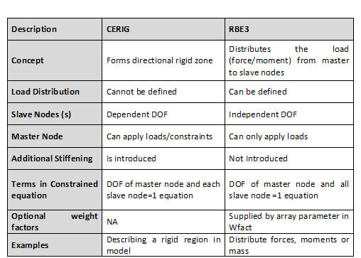
Already discussed that, both the CE’s represent the same visually in the tool but the funationality is different. To show the variation in terms of results, here we are providing a practical application results as in figure below:

Fig: CERIG and RBE3 connection – results variation resp.
This clearly states that , the following statements valid:
CERIG – produces small displacement for all the connected slave nodes , as slave nodes are dependent of master node
RBE3 – produces displacements as the weighted average of the load application according to the direction, as slave nodes are independent of master node
To conclude that, CERIG and RBE3 provide useful tools in automatically generating complex constraint equations for a variety of purposes. As with all features in simulation tool, however, it is important to understand some of the basic behaviour, such that one can use the modelling methods correctly. Since CE’s are linear, they are valid for small-rotation problems only.


